AWG cables: How they work, conversion & selection guide
The name AWG originates from a standardized wire sizing system widely used in North America to determine the diameter and cross-sectional area of a conductor. So, how do AWG cables work, how is AWG converted to mm², and how can you choose the appropriate AWG size? Learn about the operating principle, conversion formulas, and important considerations when selecting conductors in the following article.
1. What are AWG cables? Advantages of AWG cables
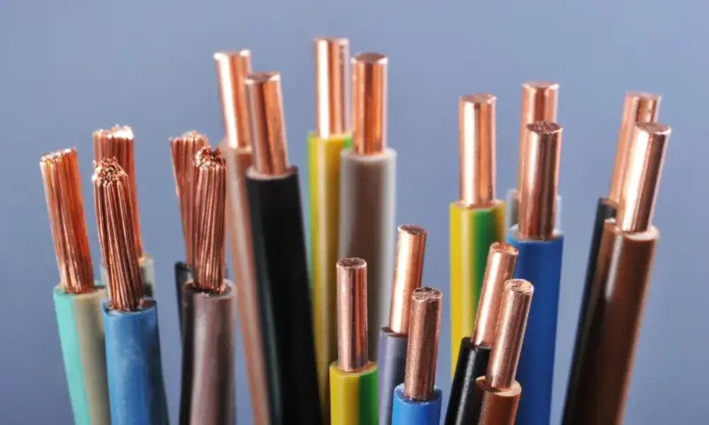
AWG (American Wire Gauge) is a standard system developed in the United States in the 19th century to standardize the measurement of electrical wire sizes. Before this system was introduced, various standards were used, making it difficult to compare specifications and potentially leading to installation errors. The adoption of AWG provides manufacturers and technicians with a common basis for determining conductor sizes.
AWG is generally used to determine the size of solid wire conductors. For stranded wire conductors, the AWG value indicates the equivalent size based on the total cross-sectional area of the individual strands.
Using the AWG system offers several benefits when selecting, designing, and installing cables:
- Standardized sizing: Makes it easier to identify and compare conductor specifications.
- Easy selection: Helps select wire sizes suitable for specific requirements.
- Electrical characteristic assessment: Helps determine the relationship between wire size, resistance, and voltage drop.
- Diverse applications: Widely used in power wires, signal cables, network cables, audio cables, and more.
- Support for safety assurance: Helps select appropriately sized wires, reducing the risk of overheating during operation.
2. Operating principle of AWG cables
According to the AWG system, wire size is represented by a number corresponding to the conductor diameter. A distinctive feature is that the smaller the AWG number, the larger the wire diameter, and vice versa. For example, AWG 16 wire has a larger diameter than AWG 20 wire. At the same time, sizes are determined according to a fixed geometric progression. Specifically, every decrease of 3 AWG sizes doubles the conductor's cross-sectional area, while every decrease of 6 AWG sizes doubles its diameter.
The conductor diameter determines its cross-sectional area, which directly affects electrical resistance. For the same material and length, a wire with a larger AWG number has lower resistance, whereas a wire with a smaller AWG number has higher resistance. This also means that wires with smaller AWG numbers generally help reduce voltage drop and power loss during current transmission, provided all other conditions remain unchanged.
💡Useful information: Why the same 2.5 mm² cable heat differently: Beyond the label?
3. Formulas for converting AWG to mm and mm²
When is it necessary to convert AWG to the meter system? Converting AWG to mm² is often necessary when importing equipment from the United States, Japan, or Taiwan, reading electrical circuit diagrams based on American standards, or selecting replacement cables compatible with the metric system. Similarly, when selecting cable lugs, connectors, or cable glands, comparing the two sizing systems helps identify suitable specifications and minimize discrepancies during installation.
To convert conductor sizes of AWG cables to the meter system, you can use formulas to calculate the conductor diameter and cross-sectional area. When determining the AWG size from a known diameter or cross-sectional area, the result is rounded to the nearest corresponding AWG size.
3.1. Formula for calculating conductor diameter (mm)
The diameter of an AWG cable with size n, denoted by dₙ, is calculated using the following formula:

Where:
- dₙ: conductor diameter, in mm
- n: AWG size to be converted
- 0.127 mm: nominal diameter of AWG 36 wire
3.2. Formula for calculating conductor cross-sectional area (mm²)
After determining the diameter, you can calculate the conductor's cross-sectional area using the following formula:

Alternatively, calculate it directly from the AWG number:

Where:
- Aₙ: conductor cross-sectional area, in mm²
- dₙ: conductor diameter, in mm
- π: the mathematical constant Pi, approximately 3.14159
- n: AWG size to be converted
4. Detailed AWG size conversion table
For convenient reference and wire selection, the following table summarizes common AWG sizes, their corresponding diameters (mm, inches), and cross-sectional areas (mm²), helping you easily compare specifications between the two sizing systems.
| AWG size | Diameter (mm) | Diameter (inch) | Area (mm2) |
| 0000 (4/0) | 11.6840 | 0.4600 | 107.2193 |
| 000 (3/0) | 10.4049 | 0.4096 | 85.0288 |
| 00 (2/0) | 9.2658 | 0.3648 | 67.4309 |
| 0 (1/0) | 8.2515 | 0.3249 | 53.4751 |
| 1 | 7.3481 | 0.2893 | 42.4077 |
| 2 | 6.5437 | 0.2576 | 33.6308 |
| 3 | 5.8273 | 0.2294 | 26.6705 |
| 4 | 5.1894 | 0.2043 | 21.1506 |
| 5 | 4.6213 | 0.1819 | 16.7732 |
| 6 | 4.1154 | 0.1620 | 13.3018 |
| 7 | 3.6649 | 0.1443 | 10.5488 |
| 8 | 3.2636 | 0.1285 | 8.3656 |
| 9 | 2.9064 | 0.1144 | 6.6342 |
| 10 | 2.5882 | 0.1019 | 5.2612 |
| 11 | 2.3048 | 0.0907 | 4.1723 |
| 12 | 2.0525 | 0.0808 | 3.3088 |
| 13 | 1.8278 | 0.0720 | 2.6240 |
| 14 | 1.6277 | 0.0641 | 2.0809 |
| 15 | 1.4495 | 0.0571 | 1.6502 |
| 16 | 1.2908 | 0.0508 | 1.3087 |
| 17 | 1.1495 | 0.0453 | 1.0378 |
| 18 | 1.0237 | 0.0403 | 0.8230 |
| 19 | 0.9116 | 0.0359 | 0.6527 |
| 20 | 0.8118 | 0.0320 | 0.5176 |
| 21 | 0.7229 | 0.0285 | 0.4105 |
| 22 | 0.6438 | 0.0253 | 0.3255 |
| 23 | 0.5733 | 0.0226 | 0.2582 |
| 24 | 0.5106 | 0.0201 | 0.2047 |
| 25 | 0.4547 | 0.0179 | 0.1624 |
| 26 | 0.4049 | 0.0159 | 0.1288 |
| 27 | 0.3606 | 0.0142 | 0.1021 |
| 28 | 0.3211 | 0.0126 | 0.0810 |
| 29 | 0.2859 | 0.0113 | 0.0642 |
| 30 | 0.2546 | 0.0100 | 0.0509 |
| 31 | 0.2268 | 0.0089 | 0.0404 |
| 32 | 0.2019 | 0.0080 | 0.0320 |
| 33 | 0.1798 | 0.0071 | 0.0254 |
| 34 | 0.1601 | 0.0063 | 0.0201 |
| 35 | 0.1426 | 0.0056 | 0.0160 |
| 36 | 0.1270 | 0.0050 | 0.0127 |
| 37 | 0.1131 | 0.0045 | 0.0100 |
| 38 | 0.1007 | 0.0040 | 0.0080 |
| 39 | 0.0897 | 0.0035 | 0.0063 |
| 40 | 0.0799 | 0.0031 | 0.0050 |
5. Criteria for selecting AWG cable cross-sectional areas
To select conductors according to the AWG standard, you need to consider the following important factors:
5.1. Conductor material
The conductive material directly affects the wire's resistance and current-carrying capacity.
- Copper: Has high electrical conductivity and generally allows a smaller cross-sectional area than aluminum under equivalent load conditions.
- Aluminum: Is lighter and can reduce material costs, but generally requires a larger cross-sectional area to achieve conductivity equivalent to copper.
5.2. Conductor construction
Conductor construction is also a factor to consider:
- Solid wire: Has a rigid structure and is suitable for certain fixed installations, such as wiring inside walls or electrical cabinets.
- Stranded wire: Consists of multiple small conductive strands and offers greater flexibility, making it suitable for moving machinery, areas subject to vibration, or locations requiring frequent bending.
5.3. Current-carrying capacity
Conductors must accommodate the circuit's maximum current to prevent overheating during operation. Depending on the application, the following AWG ranges can be used as a reference:
- Low current loads: AWG 14–18, commonly referenced for lighting systems or low-power electrical equipment.
- Medium current loads: AWG 10–12, which may be used in certain applications such as HVAC systems and high-power electrical equipment.
- High current loads: AWG 6–8 or wires with larger cross-sectional areas, depending on the requirements of applications such as EV chargers and high-power motors.
Please note that the ranges above are for reference only and are not current ratings applicable to every situation. You need to check current electrical standards and the wire's technical specifications to determine the appropriate size.
5.4. Voltage drop along the wire
When electric current flows through a conductor, resistance causes voltage drop. The longer the wire, the greater the voltage drop generally becomes, provided all other conditions remain unchanged.
Voltage drop can be calculated using the following formula: Voltage drop (V) = Current (A) × Resistance (Ω)
For example, for an AWG 16 cable with a total circuit length of 20m for the outgoing and return conductors, carrying a current of 10A and having a resistance of approximately 0.263Ω, the voltage drop will be 2.63V. With a 12V power supply, this voltage drop accounts for approximately 21.9%, which is relatively high. In this case, you may consider using a wire with a larger cross-sectional area, such as AWG 14 or AWG 12, to reduce the voltage drop.
5.5. Installation environmental conditions
Temperature, humidity, UV radiation, and chemicals can affect the durability of the insulation as well as the conductor's operating performance.
- High-temperature environments: Select wires with insulation materials and temperature ratings suitable for the conditions. Current-carrying capacity may need to be derated according to actual operating conditions.
- Outdoor installations: Use wires with insulation or protective sheathing suitable for UV exposure and weather conditions.
- Areas with chemicals or high humidity: Consider chemical resistance, moisture resistance, and the system's protection requirements.
6. AWG cable sizes for common applications
For reference when selecting AWG cables, please check the following table:
| Reference AWG size | Common applications |
| AWG 14–18 | Residential lighting systems, depending on current load and wire length. |
| AWG 14–16 | Certain low-power electrical devices, depending on operating specifications. |
| AWG 10–12 | Certain high-power devices and HVAC systems, depending on electrical load requirements. |
| AWG 6–8 or smaller AWG numbers | High-current applications, such as large motors or EV charging systems, depending on system design. |
| AWG 4 or smaller AWG numbers | Large industrial equipment, main power cables, sub-distribution panels, etc. |
For wire runs longer than 50 ft (15.24 m), you should consider using a wire with a larger cross-sectional area (corresponding to a smaller AWG number) to limit voltage drop. In addition, when selecting AWG cables for outdoor systems or machinery that moves frequently, remember to consider the current load, installation conditions, and requirements for insulation and conductor flexibility to ensure suitability for the operating environment.
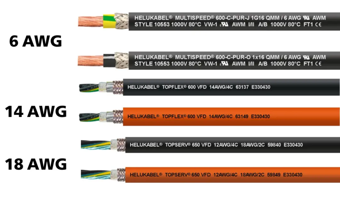
7. Recommended AWG cables from HELU
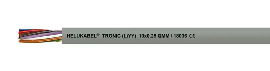
We HELU Vietnam offer a range of AWG 18 and AWG 16 cables designed to meet various industrial applications and installation requirements. Refer to the table below to explore the key features of each cable series and identify the right product for your needs.
7.1. 18 AWG cables from HELU
| Product series | Key features |
| HELUDATA UL 2092 | 1 × 2 × 18 AWG | Suitable for fixed installation; operating temperature: -30°C to +60°C; maximum operating voltage: 300 V. |
| TRONIC (LiYY) grey 2 × 1 mm² | Flexible cable suitable for designs requiring a small outer diameter. |
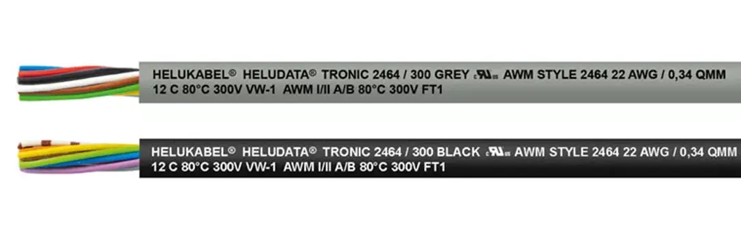
| HELUDATA® TRONIC-CY 2464 / 300 BLACK 2 × 18 AWG | Flexible data cable approved by UL/CSA for control, measurement, signal and pulse technology applications. |
| TRONIC-CY (LiY-CY) grey 2 × 1 mm² | Flexible cable with shielding, suitable for applications requiring protection against electromagnetic interference. |
| PAAR-TRONIC-CY grey 1 × 2 × 1 mm² | Suitable for control and signal transmission in environments with electromagnetic interference risks; designed for flexible, free movement without tensile stress. |
7.2. 16 AWG cables from HELU
| Product series | Key features |
| HELUDATA UL 2464 | 1 × 2 × 16 AWG | Data cable for fixed installation; maximum operating voltage: 300 V; core-to-core test voltage: 1,000V. |
| TOPFLEX® 600 VFD black 4 × AWG 16 | Highly oil-resistant motor cable with double shielding for effective protection against electrical interference. |
| HELUDATA® TRONIC 2464 / 300 BLACK 3 × 16 AWG | Flexible data cable approved by UL/CSA for signal and measurement applications in industrial environments. |
| TRONIC (LiYY) grey 2 × 1.5 mm² | Flexible cable suitable for both fixed installation and moving applications. |
| TRONIC-CY (LiY-CY) grey 2 × 1.5 mm² | Flexible shielded cable suitable for signal transmission applications requiring protection against electromagnetic interference. |
8. Frequently asked questions about AWG cables
AWG (American Wire Gauge) is a standardized wire sizing system widely used in North America. It classifies conductors based on their diameter, with smaller AWG numbers indicating larger wire diameters and cross-sectional areas.
AWG cables are used to transmit electrical power, signals, and data in electronic devices, industrial control systems, machinery, and other electrical applications.
The current-carrying capacity of AWG cables depends on the wire size, conductor material, ambient temperature, and installation conditions. Refer to ampacity tables and the manufacturer's datasheet to select the appropriate cable.
The higher the AWG number, the smaller the conductor, and vice versa. For example, AWG 12 wire has a larger diameter than AWG 16 wire. Conductor size affects resistance, current-carrying capacity, and voltage drop along the wire.
No. AWG size is determined by the diameter of the metal conductor, excluding the outer insulation. The overall diameter of a wire or cable also depends on the thickness of the insulation, sheathing, and cable construction.
16 AWG wire has a diameter of approximately 1.29 mm, equivalent to a cross-sectional area of about 1.31 mm².
18 AWG wire has a diameter of approximately 1.02 mm, equivalent to a cross-sectional area of about 0.823 mm².
AWG can be converted to mm² using a formula to calculate the cross-sectional area based on the AWG number or by referring to a standard conversion table. Note that the calculated result does not always exactly match the nominal cross-sectional area of commercially available conductors.
AWG cable selection should be based on load current, wire length, permissible voltage drop, conductive material, and installation conditions. In addition, applicable standards and the manufacturer's guidelines must be checked to ensure that the conductor meets technical and safety requirements.
AWG and mm² are two ways of expressing conductor size. AWG uses a numerical wire sizing system, while mm² directly represents the cross-sectional area of the conductor. AWG is common in North America, whereas mm² is widely used in international standards and technical documentation.
Replacement may be considered if the conductor meets the technical requirements of the application. However, you should not rely solely on a nearly equivalent cross-sectional area. You must also check current-carrying capacity, rated voltage, operating temperature, insulation material, and connector compatibility.