Why the same 2.5 mm² cables heat differently: Beyond the label
Before your next electrical cable installation, try answering this question: two cables both marked with a 2.5 mm² conductor cross section, the same PVC jacket, the same color — do they conduct electricity equally well? If your answer is yes, this article is for you.
1. Nominal, Design, and Actual cross section — Three concepts commonly confused
It is important to distinguish between three concepts: nominal cross-section, design cross-section, and actual cross-section
1.1 The difference between the three cross section concepts
When discussing conductor cross sections, most technicians are familiar with only one number: the figure printed on the cable surface. In reality, three entirely distinct concepts exist side by side — and confusing them is the root cause of many incorrect wire selection decisions.
- Nominal cross section is the number printed on the cable surface — for example 1.5 mm², 2.5 mm², 4 mm²... According to IEC 60228 (TCVN 6610-1:2014), this is not a measured value, carries no direct tolerance, and does not require verification by measuring geometric area. It is simply a specification grade label — used for design documentation lookup, project filing, and production management.
- Design cross section (also called the electrical cross section) is the cross section calculated in reverse from the maximum DC resistance requirement. This is the parameter that actually controls conductor quality. When a manufacturer designs the conductor core for the 2.5 mm² grade, they do not draw a circle with exactly 2.5 mm² area and cut copper to match — instead they work backwards: given the resistivity of the material being used, how much cross section is needed to meet the specified maximum resistance? That figure is the design cross section.
- Actual cross section is the geometric area measured directly on the conductor's cross-sectional face. And here is what surprises many people: the actual cross section can be smaller than the nominal cross section and still be fully compliant - if the manufacturer uses copper with higher conductivity than the minimum standard requires. Conversely, an actual cross section larger than nominal does not guarantee compliance if the copper has low purity.
In other words: the only valid measure for evaluating conductor quality is DC resistance - not geometric area.
1.2 Practical impact — Why the same 2.5 mm² cross section can have different resistance
According to IEC 60228, a 2.5 mm² Class 5 conductor (flexible stranded conductor, widely used in electrical installations) must have a DC resistance not exceeding 7.98 mΩ/m at 20°C. This is a maximum threshold - meaning a manufacturer can supply cable with resistance of 7.0 mΩ/m or 7.9 mΩ/m and both are considered "compliant."
Two cables both marked 2.5 mm², one with an actual resistance of 7.1 mΩ/m and one at 7.9 mΩ/m — both pass the standard on paper, but when carrying the same 20A current, the heat generated will differ noticeably. And when a substandard manufacturer pushes resistance above the permitted threshold — even by just 10–15% — the difference begins to manifest as elevated surface temperature.
Understanding this helps explain why two cables both marked 2.5 mm² can generate entirely different amounts of heat during operation. However, DC resistance is just one of three factors that create this difference — the other two lie deeper inside the conductor structure.
Learn about the classification of conductors according to IEC 60228

2. Conductor fill factor and its effect on cross section quality
2.1 What is fill factor in a stranded conductor?
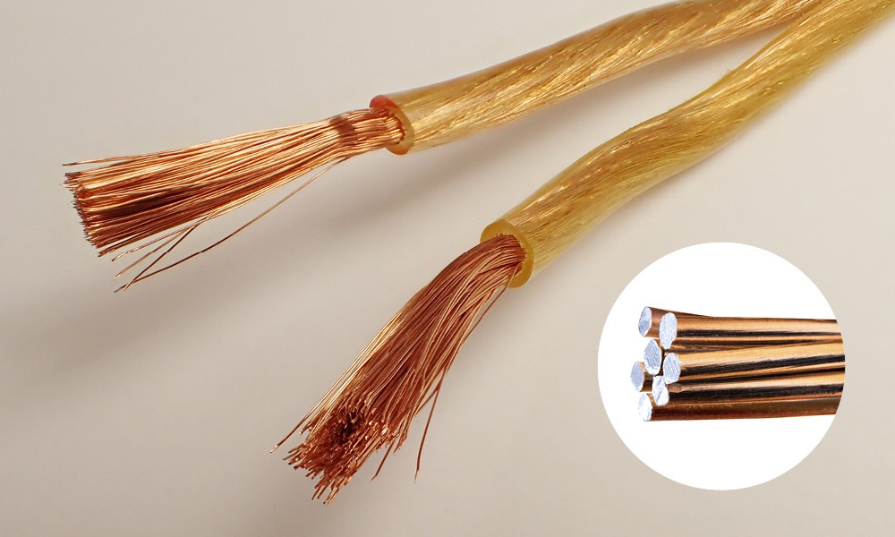
Unlike solid conductors, stranded conductors consist of multiple small copper wires twisted together. Geometrically, circular wires placed side by side cannot completely fill the available space — air gaps always exist between the strands.
Fill factor is the ratio of the total actual copper cross section of the individual strands to the cross-sectional area of the smallest circle enclosing the entire conductor bundle. In practical terms: within each mm² viewed from the cross section, only a fraction is actual conducting copper — the rest is air.
For Class 5 conductors per IEC 60228 — the flexible multi-strand wire commonly used in electrical installations — the fill factor typically reaches 75–85%. This is entirely normal: IEC 60228 accounts for this reality when setting maximum resistance thresholds.

2.2 How fill factor creates quality differences
The problem does not lie in the normal fill factor of a stranded conductor — it lies in the fact that this is the easiest parameter to manipulate during manufacturing without it being visible externally.
When a manufacturer deliberately uses fewer strands or thinner strands than the standard design requires, the fill factor drops below the permitted level. Externally, the overall conductor diameter still appears similar — because the increased air gaps between strands compensate for the reduced copper. But the actual copper conducting electricity is less, resistance is higher, and more heat is generated during operation.
IEC 60228 controls this by specifying the maximum wire diameter for each cross section grade and conductor class. For example, a 2.5 mm² Class 5 conductor must have strands with an individual diameter not exceeding 0.26 mm. A manufacturer using 30 strands of 0.32 mm diameter may achieve a numerically similar total cross section — but the electrical and mechanical properties will differ significantly, and crucially, the actual DC resistance will exceed the permitted limit.
This is why DC resistance measurement is always the most reliable quality check: it simultaneously reflects both fill factor and copper purity — two factors that are completely indistinguishable to the naked eye.
3. Copper purity and its effect on conductor quality
CCA wire (Copper-Clad Aluminum): the core is aluminum, with only a thin layer of copper on the outside
3.1 What is copper purity and why does it matter?
Even when the cross section is correct and the fill factor meets the standard, a cable can still conduct electricity poorly if the core material quality is substandard.
Not all copper wire conducts electricity equally — even though they look nearly identical from the outside.
The international standard measure for the electrical conductivity of a material is IACS (International Annealed Copper Standard), where pure copper is set as the 100% benchmark. Copper grades CDA 101 and CDA 102 (purity ≥99.99%) achieve exactly 100% IACS — this is the copper grade that IEC 60228 uses as the basis for calculating maximum resistance thresholds for each cross section grade.
When impurities appear in copper, conductivity decreases even at concentrations of parts per million (ppm). A more common situation in the market is CCA wire (Copper Clad Aluminium): an aluminium core with only a thin copper coating on the outside. From the outside, CCA wire looks almost identical to pure copper wire — but the conductivity difference is substantial:
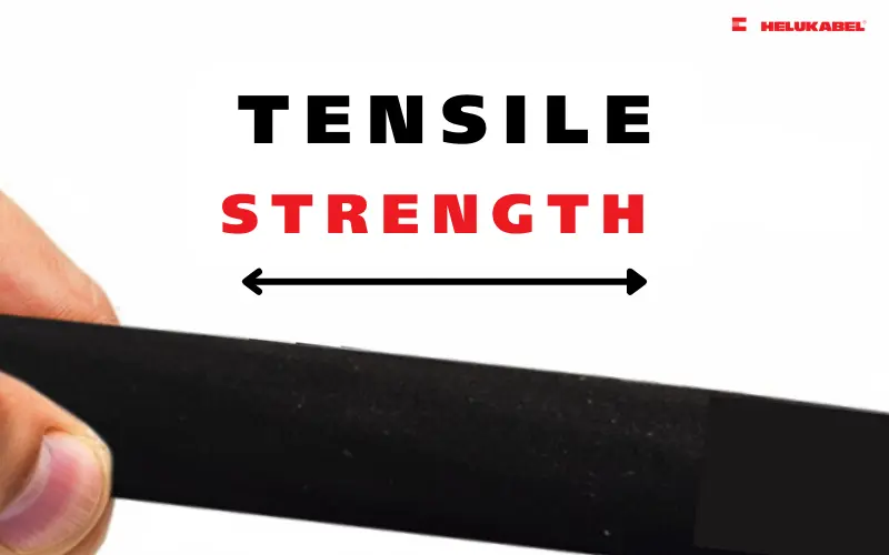
| Alloy | Chemical composition | Tensile strength | IACS conductivity at 20°C (68°F) | |
| Aluminum | 1350 | 99.5% Aluminum | 82.7 MPa (12.0 ksi) | 61.2 |
| 8176 | 98.5% Aluminum | 117 MPa (17.0 ksi) | 65.2 | |
| Copper | CDA 10100 | 99.99% | 379 MPa (55.0 ksi) | 100 |
| CDA 10200 | 99.5% | 379 MPa (55.0 ksi) | 100 | |
| CDA 1100 | 99.99% | 379 MPa (55.0 ksi) | 100 | |
| CCA | 10% CCA | 10% copper by volume | 82.7 MPa (12.0 ksi) | 62.9 |
| 15% CCA | 15% copper by volume | 117 MPa (17.0 ksi) | 64.4 |
3.2 How copper purity creates quality differences
Lower conductivity means higher resistance on the same conductor cross section — and by Joule's Law (P = I²R), higher resistance directly generates more heat when operating under the same load.
A concrete example: if a cable with a nominal 2.5 mm² cross section uses a CCA 10% instead of pure copper, conductivity reaches only 62.9% IACS — meaning DC resistance is approximately 59% higher than a pure copper cable of the same nominal cross section (calculated as R_CCA/R_Cu = 100/62.9 = 1.59). This far exceeds the IEC 60228 permitted threshold and generates significantly more heat on the same cable run, same load, every hour of operation.
Numerical example: 2.5 mm² cable carrying 20A
| Cable quality | Resistivity (Ω/km) | Heat generated (W/m) |
| Meets IEC standards (typical) | 7.10 | 2.84 W/m |
| At IEC maximum threshold | 7.98 | 3.19 W/m |
| Substandard (exceeds IEC standards) | 9.50 | 3.80 W/m |
The difference between compliant and substandard cable may appear small, but that heat accumulates continuously inside the PVC insulation. Over time, the elevated temperature accelerates PVC degradation — the jacket becomes brittle and develops cracks. This is the root cause of many electrical faults that occur 3–5 years after installation, when the cable still appears "normal" from the outside.
4. How to verify conductor quality
Now that you understand why two cables with the same 2.5 mm² conductor cross section can generate entirely different amounts of heat during operation — nominal cross section is not a quality criterion, fill factor can be reduced without visible signs, and core material directly affects actual resistance — the practical question is: how do you detect and prevent this before installation?
4.1 Method 1: DC resistance measurement
Use a milliohmmeter or a digital multimeter with a mΩ range. Cut a length of exactly 1 metre, measure the resistance across both ends of the conductor core, and compare against the table below. If the measured resistance exceeds the maximum value — the cable does not meet the standard.
| Nominal cross-section | Class 1 (solid) | Class 2 (stranded) | Class 5 (flexible) |
| 1.5 mm² | ≤12.1 mΩ/m | ≤12.1 mΩ/m | ≤13.3 mΩ/m |
| 2.5 mm² | ≤7.41 mΩ/m | ≤7.41 mΩ/m | ≤7.98 mΩ/m |
| 4 mm² | ≤4.61 mΩ/m | ≤4.61 mΩ/m | ≤4.95 mΩ/m |
| 6 mm² | ≤3.08 mΩ/m | ≤3.08 mΩ/m | ≤3.30 mΩ/m |
| 10 mm² | ≤1.83 mΩ/m | ≤1.83 mΩ/m | ≤1.91 mΩ/m |
4.2 Method 2: Individual wire diameter measurement against IEC 60228
Separate a short section of conductor, extract one individual wire strand and measure its diameter with a vernier caliper. Compare against the maximum wire diameter limits per IEC 60228:
| Nominal cross-section | Maximum wire diameter (Class 5) |
| 1.5 mm² | 0.26 mm |
| 2.5 mm² | 0.26 mm |
| 4 mm² | 0.31 mm |
| 6 mm² | 0.31 mm |
| 10 mm² | 0.41 mm |
If the measured wire diameter exceeds the maximum value in the table, the cable does not meet Class 5 requirements. The manufacturer has used fewer, thicker strands to achieve the nominal cross section — resulting in a lower fill factor and reduced flexibility.
Limitation: this method only detects structural issues with the strand configuration. It does not replace DC resistance measurement — a cable may have correct wire diameters but still use low-purity copper.
4.3 Method 3: Select a supplier with certified quality control
The two methods above are useful when you need to test cable already on hand. The most effective prevention, however, is eliminating the problem at the supplier selection stage.
A reputable wire and cable manufacturer controls quality across all three factors analyzed above: verifying incoming copper purity, controlling strand structure per IEC 60228, and measuring the DC resistance of every production batch before dispatch. These commitments cannot be self-declared — they must be confirmed by independent third parties through internationally recognized certifications.
Key certifications to look for when selecting a supplier:
- VDE: one of the most rigorous certifications for wire and cable, requiring periodic factory audits and random market sampling. VDE-marked cables can be verified directly on the public database at vde.com.
- HAR: the European harmonized certification, recognized by testing organizations across 27 member countries.
- CE Marking: mandatory for cables placed on the EU market, confirming compliance with the Low Voltage Directive (LVD) and Electromagnetic Compatibility (EMC) Directive.
- TCVN: the Vietnamese national standard equivalent to IEC 60228, mandatory for cables distributed within Vietnam. Products with TCVN certification must pass testing at organizations designated by the Ministry of Industry and Trade.

We hope this article has helped you see the 2.5 mm² conductor cross section figure in a new light — not as a quality specification, but as the starting point of a quality story. What determines whether a cable operates safely throughout its service life or generates abnormal heat after a few years lies in factors that never appear on the label.
At HELU, we publish full technical specifications for every product in the accompanying datasheet — including actual DC resistance values, conductor construction details, and certifications including VDE and HAR. If you need technical support selecting the right cable for a specific application, our engineering team is ready to assist.
5. FAQs
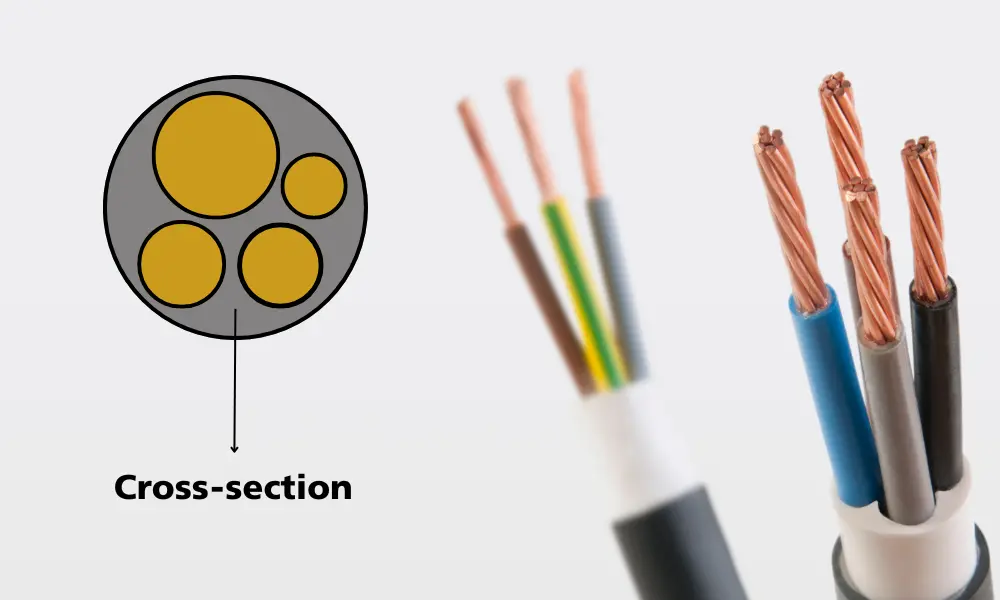
5.1 What is conductor cross section of cable?
The conductor cross-sectional area is the cross-sectional area of the inner conductive core, measured in mm². However, the number printed on the cable jacket — for example 1.5 mm² or 2.5 mm² — is the nominal cross section: a specification grade label, not a direct measurement result. Per IEC 60228, conductor quality is controlled through maximum DC resistance values, not by directly measuring geometric area.
5.2 What does IEC 60228 specify about conductor cross sections?
IEC 60228 is the international standard for conductors of insulated cables. It classifies conductors into classes (1, 2, 5, 6...) and specifies the maximum DC resistance per unit length at 20°C for each cross section grade, along with minimum strand counts and maximum individual wire diameters for each class. Notably, IEC 60228 does not require direct measurement of geometric area — the nominal cross section carries no measurement tolerance, and quality is assessed entirely through DC resistance.
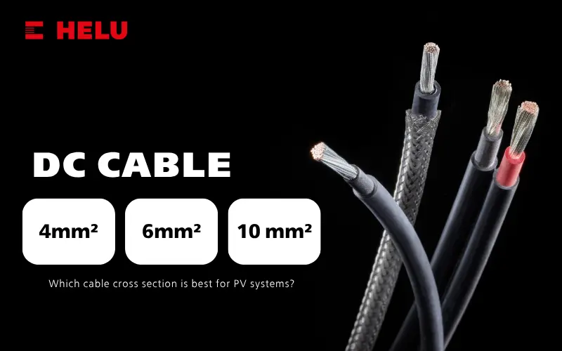
5.3 How much current can a 2.5 mm² conductor carry?
A 2.5 mm² Class 5 conductor compliant with IEC 60228 can carry approximately 16–25A depending on installation conditions — cables run in open air can carry higher current than those installed in conduit or buried in walls due to differences in heat dissipation. This figure applies only to pure copper conductors meeting the standard. CCA wire or cable with actual DC resistance exceeding the IEC 60228 threshold generates more heat at the same load, meaning the safe operating current is lower than the theoretical value.
5.4 Does the PVC jacket affect operating temperature?
Yes — but in the opposite direction from what many people expect. The PVC jacket does not generate heat, but it acts as a thermal barrier that retains heat produced by the copper conductor. Good quality PVC insulation withstands continuous operating temperatures up to 70°C (standard PVC) or 90°C (heat-resistant PVC). When substandard cable generates more heat than its design allows, the core temperature rises beyond the jacket's tolerance — the PVC begins to degrade, plasticisers volatilise, and the jacket becomes brittle and cracks. This is why substandard cable typically fails at the jacket before the conductor breaks.
5.5 What units are used to measure conductor cross section?
Two measurement systems are in parallel use internationally. The metric system (IEC/European) uses mm² (square millimetres) — the standard in Vietnam, Europe, and most countries applying IEC standards. The imperial system (North America) uses AWG (American Wire Gauge) — a higher AWG number means a smaller wire, the opposite of mm² where a larger number means a larger wire. For large power cables in the US, kcmil (or MCM) is also used — 1 kcmil = 0.5067 mm². Confusion between these systems when working with technical documentation from different origins is a common cause of incorrect wire selection.
Learn about the AWG rating and the AWG-to-mm² conversion chart