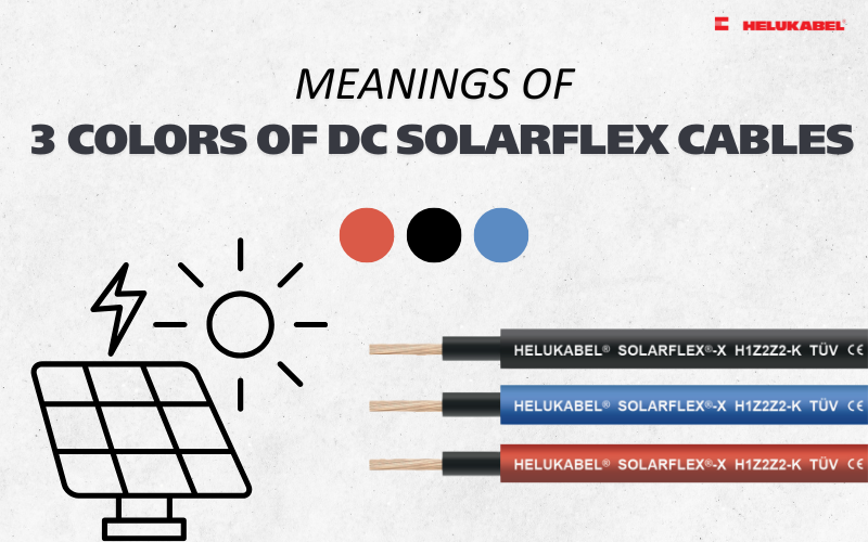
4mm², 6mm², or 10mm² DC cables: Which cable cross section is best for PV systems?
Should you choose 4 mm², 6 mm², or 10 mm² DC cable? Discover the differences and learn how to select the right cable size for your specific PV system requirements.
Selecting the correct DC cable cross-section is one of the most critical factors in determining the efficiency and long-term reliability of a solar system. Among the available options, 4 mm², 6 mm², and 10 mm² cable sizes are the most commonly used standards, thanks to their flexibility in accommodating a wide range of installations - from residential rooftop systems to commercial and industrial applications.
Each cable size has its own characteristics in terms of current-carrying capacity, voltage drop, and application scope. Understanding these differences is essential for choosing the right solution, optimizing system performance, and ensuring compliance with technical standards. In this article, we will provide a detailed comparison of 4 mm², 6 mm², and 10 mm² DC cables, helping you determine the most suitable option for your specific application.
1. Importance of DC cable cross section in solar systems
Choosing the right DC cable directly affects the operational performance and safety of the entire system
Selecting the appropriate DC cable size is not just a technical requirement - it is a critical factor that directly impacts the performance, safety, and overall cost efficiency of a PV system.
- Performance: Choosing the correct cable cross-section helps minimize power losses during transmission, ensuring that most of the generated energy is effectively delivered to the inverter and other system components. This is especially important in large-scale systems or installations with long cable runs. If the cable size is insufficient for the current, voltage drop will occur. For example, a 3% voltage drop means a 3% loss in energy output. Over a typical system lifespan of 25 years, this represents a significant cumulative loss.
- Safety: Undersized cables can become overloaded, leading to overheating and potential damage to the insulation. Excessive heat accelerates insulation aging and increases the risk of electrical faults or even fire hazards. DC cables that consistently operate at elevated temperatures are unlikely to achieve their expected service life of 25–30 years. In many cases, premature failure can occur, resulting in costly replacements - especially after the system has already been installed.
- Cost efficiency: Oversizing cables improves safety but increases material and installation costs. On the other hand, undersized cables may reduce upfront costs but lead to higher energy losses and potential maintenance or replacement expenses in the long run. Therefore, selecting the optimal cable size is essential to achieving the right balance between performance, safety, and total investment cost.
2. Technical comparison of 4 mm², 6 mm² ,10 mm² DC cables
A larger cross-sectional area helps reduce the resistance of the conductor, thereby reducing voltage drop along the line
2.1 Cable cross section
The fundamental difference between 4 mm², 6 mm², and 10 mm² DC cables lies in the conductor cross-sectional area, which refers to the surface area of the metal conductor (typically copper) inside the cable:
- 4 mm² DC cable: Conductor cross-section of 4 mm²
- 6 mm² DC cable: Conductor cross-section of 6 mm²
- 10 mm² DC cable: Conductor cross-section of 10 mm²
The larger the cross-sectional area, the greater the cable’s ability to conduct electrical current. This directly impacts several key technical factors:
- Current-carrying capacity: Cables with larger cross-sections can carry higher current without overheating. This makes them suitable for systems with higher power output or higher string currents.
- Voltage drop: A larger cross-section reduces the electrical resistance of the conductor, thereby minimizing voltage drop along the cable. This is particularly important in PV systems, where excessive voltage drop can significantly reduce overall system efficiency. For the same current and cable length, a 10 mm² cable will exhibit substantially lower voltage drop compared to a 4 mm² cable.
- Energy loss and system efficiency: Lower resistance results in reduced power loss (in the form of heat). Therefore, selecting an appropriate or slightly larger cable size helps improve long-term system efficiency and performance.
FAQ with HELU: What factors determine a cable’s current-carrying capacity?
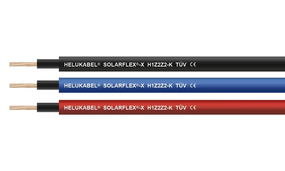
SOLARFLEX®-X H1Z2Z2-K DC cable with a cross-sectional area ranging from 2.5 to 240 mm²
2.2 Current-carrying capacity of DC cables
Current-carrying capacity (ampacity) refers to the maximum current a cable can continuously carry under specified conditions without exceeding the permissible temperature limit of its insulation. This is a critical parameter in PV system design to ensure both safety and cable lifespan.
The conductor cross-section (mm²) is the primary factor influencing ampacity. A larger cross-section results in lower electrical resistance and reduced heat generation, allowing the cable to carry higher current without overheating.
For our SOLARFLEX®-X H1Z2Z2-K DC cable, the typical current-carrying capacities are as follows:
| Cross-section | Single core laying freely in air (*) In accordance with EN 50618 | Single core on surface In accordance with EN 50618 | Two cables touching on surfaces In accordance with EN 50618 | Two loaded cables touching directly buried in soil (**) In accordance with IEC 60364-5-52 |
| 4 mm² | 55 | 52 | 44 | 46 |
| 6 mm² | 70 | 67 | 57 | 58 |
| 10 mm² | 98 | 93 | 79 | 77 |
| These values are subject to change without prior notice. Please contact HELU Vietnam technical support team for the most up-to-date data. | ||||
Notes:
(*) Ambient temperature: +60 °C
(**) Soil temperature: +20 °C, installation method D2 according to IEC 60364-5-52, burial depth up to 0.8 m
In real-world PV installations, cables are often installed on rooftops or outdoors, where temperatures can be significantly higher than standard conditions. As ambient temperature increases, the cable’s ability to dissipate heat decreases, which in turn reduces its effective current-carrying capacity. Therefore, it is essential to apply appropriate conversion factors when actual installation conditions differ from standard assumptions.
| Temperature | Conversion factor |
| Up to +60 °C | 1.00 |
| 70 °C | 0.92 |
| 80 °C | 0.84 |
| 90 °C | 0.75 |

2.3 Voltage drop
Voltage drop refers to the reduction in voltage as electrical current flows through a conductor, primarily caused by the cable’s resistance. In PV systems, voltage drop is a critical factor because it directly impacts system efficiency, energy losses, and overall operational stability.
The cable cross-section (mm²) has a direct relationship with voltage drop:
- A larger cross-section means lower resistance and lower voltage drop
- A smaller cross-section means higher resistance and higher voltage drop
For the three common DC cable sizes:
- 4 mm² DC cable: Higher resistance, resulting in greater voltage drop - especially over long cable runs
- 6 mm² DC cable: Lower resistance than 4 mm², significantly reducing voltage drop
- 10 mm² DC cable: Much lower resistance, delivering minimal voltage drop, particularly effective for long-distance runs or high-power systems
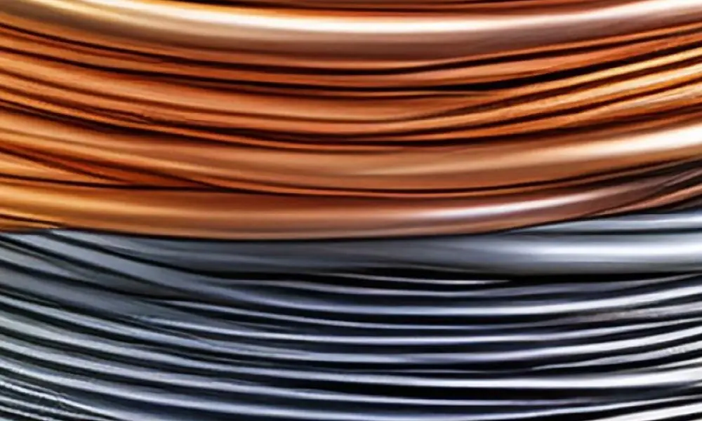
As the cross-sectional area of the DC conductor increases, the amount of conductive material (copper/aluminum) increases, thereby increasing the overall weight of the cable
2.4 Weight and flexibility considerations
In addition to electrical parameters such as ampacity and voltage drop, the cable cross-section also directly affects the weight and flexibility of DC cables, which in turn influences installation and handling.
In principle, as the cross-section increases:
- The amount of conductive material (copper or aluminum) increases, leading to higher cable weight
- The overall cable diameter becomes larger, which means reduced flexibility and larger minimum bending radius
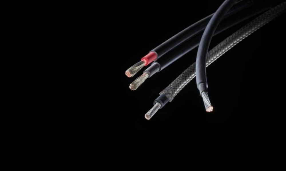
Take, for example, our SOLARFLEX®-X H1Z2Z2-K and SOLARFLEX®-X H1Z2Z2-K NTS (rodent-resistant version) DC cables:
| Cross-section | SOLARFLEX®-X H1Z2Z2-K | SOLARFLEX®-X H1Z2Z2-K NTS | ||||
| Cu factor per km (kg/km) | Weight kg/km, approx. | Outer diameter (min - max) | Cu factor per km (kg/km) | Weight kg/km, approx. | Outer diameter (min - max) | |
| 4 mm² | 38.4 | 59.0 | 5.2–5.9 | 38.4 | 85.0 | September 5 – June 6 |
| 6 mm² | 57.6 | 80.0 | May 8 – June 4 | 57.5 | 112.0 | 6.5 – 7.1 |
| 10 mm² | 96.0 | 125.0 | June 9 – July 7 | 96.0 | 158.0 | July 6 – August 4 |
- 4 mm² DC cable: Lightweight and highly flexible, making it easy to bend, route, and install. This cable size is particularly suitable for small-scale residential PV systems, where installation space is limited and flexible cable routing on rooftops is required.
- 6 mm² DC cable: Heavier and slightly less flexible than 4 mm², but still offers adequate flexibility for most practical applications. It is the most commonly used option, providing a good balance between electrical performance and ease of installation.
- 10 mm² DC cable: Significantly heavier with a larger overall diameter, resulting in noticeably reduced flexibility.
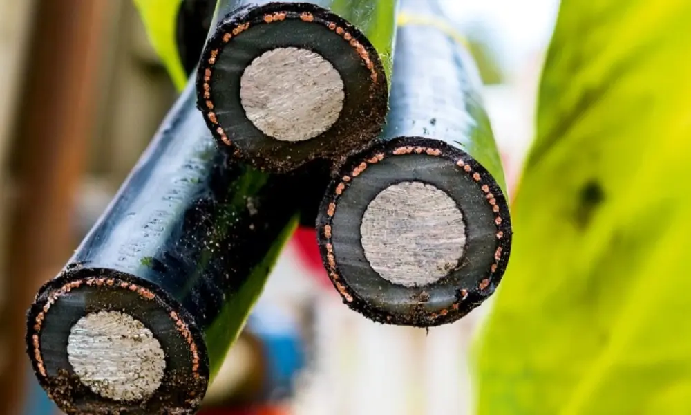
In environments where cables must be buried directly, soil thermal resistivity can also influence the selection of the cable cross-sectional area
2.5 Installation environment and its impact on DC cable cross section
The selection of DC cable size (4 mm², 6 mm², 10 mm²) is not determined solely by current and voltage drop. It is also indirectly influenced by the installation environment, which can dictate the required cable construction (sheath, protective layers, armoring). These factors, in turn, affect heat dissipation, cable weight, and ultimately the appropriate cable size.
In environments with a high risk of rodent damage, such as industrial sites or outdoor installations, it is recommended to use armoured DC cables. For example, the SOLARFLEX®-X H1Z2Z2-K NTS (rodent-resistant version) includes an armour layer. However, this added protection increases the cable’s outer diameter and weight, which can reduce heat dissipation. As a result, it may be necessary to increase the cable cross section (e.g., from 6 mm² to 10 mm²) to maintain safe operating conditions.
For direct burial installations, the soil thermal resistivity (K x m/W) becomes a critical factor. Soil with high thermal resistivity (≥ 2.5 K x m/W), such as dry or sandy soil, has poor heat dissipation characteristics. In such conditions, using 4 mm² or 6 mm² cables may lead to overheating. Therefore, a larger size such as 10 mm² is often required to ensure safe and reliable operation.
When soil conditions deviate from the standard reference value of 2.5 K x m/W, it is necessary to apply correction factors to adjust the current-carrying capacity. For our SOLARFLEX®-X H1Z2Z2-K cable range, the corresponding correction factors are provided as follows:
| Thermal resistivity, K x m/W | 0.5 | 0.7 | 1 | 1.5 | 2 | 2.5 | 3 |
| Correction factor for cables in buried ducts | 1.28 | 1.20 | 1.18 | 1.10 | 1.05 | 1.00 | 0.96 |
| Correction factor for direct buried cables | 1.88 | 1.62 | 1.5 | 1.28 | 1.12 | 1.00 | 0.90 |
| These values are subject to change without prior notice. Please contact HELU Vietnam technical support team for the most up-to-date data. | |||||||
3. Common applications of 4 mm², 6 mm², and 10 mm² DC cables
4 mm² DC cable is commonly used for short connections, typically under 10–15 m
Selecting the appropriate DC cable cross section (4 mm², 6 mm², or 10 mm²) plays a crucial role in ensuring both the performance and safety of a solar PV system. Each cable cross section has distinct characteristics in terms of electrical capacity, cost, and flexibility, making it suitable for different installation conditions and system scales.
3.1 Applications of 4 mm² DC cable
For small-scale systems, especially residential rooftop installations, 4 mm² DC cables are commonly used for short connections, typically under 10-15 meters. At this distance, current levels remain moderate (around 25–30 A), and voltage drop can be effectively kept below 2%. Thanks to their lightweight structure, high flexibility, and lower cost, 4 mm² cables are ideal for compact system layouts where the inverter is located close to the PV modules. However, when the cable length increases to around 30–40 meters, voltage drop becomes significant, making this size unsuitable for longer runs.
In larger residential or standard commercial systems, 6 mm² DC cables have become a popular choice
3.2 Applications of 6 mm² DC cable
For larger residential systems or standard commercial installations, 6 mm² DC cables are the most commonly used option. They are well-suited for medium cable runs (typically 20–50 meters), where higher current levels and stricter voltage drop control are required. Compared to 4 mm², the larger cross-section significantly reduces electrical resistance, minimizing energy losses and ensuring stable system performance. This makes 6 mm² the best balance between cost and performance, and the standard choice in most PV installations.
3.3 Applications of 10 mm² DC Cable
For large-scale systems or long-distance cable runs, 10 mm² DC cables become essential. In commercial or utility-scale projects, cable lengths can exceed 50–100 meters, where voltage drop becomes a critical design factor. With much lower resistance, 10 mm² cables effectively reduce energy losses and maintain optimal performance even under high current conditions. They are also well-suited for harsh installation environments, such as high temperatures, direct burial, or bundled cable installations where heat dissipation is limited. However, these advantages come with higher material and installation costs, as well as stricter handling requirements.

4. Common mistakes to avoid when sizing DC cables for PV systems
Incorrect DC cable sizing can significantly reduce system efficiency and introduce safety risks. Below are the most common mistakes to avoid when designing and selecting DC cable sizes:
- Ignoring voltage drop: One of the most frequent mistakes is focusing only on current-carrying capacity while neglecting voltage drop. For example, a 4 mm² cable may perform well at 10–15 meters, but extending it to 30–40 meters can result in excessive voltage drop and reduced system efficiency. In such cases, upgrading to 6 mm² or larger is necessary.
- Underestimating cable length: Designers often calculate only the one-way distance and ignore the round-trip cable length, leading to inaccurate sizing. Since voltage drop increases proportionally with length, this can result in undersized cables.
- Ignoring ambient temperature: Current ratings are typically based on standard conditions (around 60°C ambient for DC cables), but real-world installations can exceed this. Higher temperatures reduce ampacity by up to 25%, requiring derating or larger cable cross section (upgrading from 6 mm² to 10 mm²). This is a common issue in tropical climates.
- Poor installation practices: Improper installation, such as excessive bending, tight bundling, or mechanical damage, can increase localized resistance, create hot spots, and reduce current-carrying capacity. Failure to follow minimum bending radius requirements or ensure long-term UV resistance can also negatively impact cable performance and lifespan.
5. HELU DC cable portfolio (4 mm², 6 mm² & 10 mm²)
HELU offers a comprehensive range of 4 mm², 6 mm², and 10 mm² DC cables, designed to meet diverse installation conditions across PV systems:
- SOLARFLEX®-X H1Z2Z2-K: Eca and Dca CPR class
- HELUPOWER® SOLARFLEX®-X PREMIUM: The version for floating solar power systems
- HELUPOWER® SOLARFLEX®-X H1Z2Z2-K UL: UL 2000 V DC
- SOLARFLEX®-X H1Z2Z2-K NTS: rodent-resistant version, Eca CPR

In addition to standard DC cable sizes, HELU provides a full ecosystem of products and solutions for solar power systems:
- DC cables with cross-sections ranging from 2.5 mm² to 240 mm², available in both copper and aluminum conductors
- AC power cables and communication cables
- Specialized cables for BESS systems, such as HELUPOWER® HIGH AMP-X
- DC connectors, including MC4-Evo2A
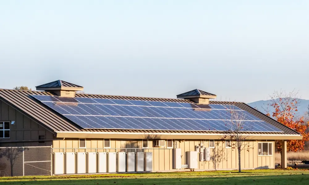
- A comprehensive product ecosystem supporting both residential and industrial applications, including inverters, energy storage systems (BESS), and AC EV charging solutions

Products and solutions for PV systems
If you still have questions, don’t hesitate to contact HELU Vietnam’s team of engineers for detailed answers.
HELU Vietnam Contact Information
| HELU Vietnam 905 Nguyen Kiem Street , Hanh Thong Ward, Ho Chi Minh City, 700000, Vietnam | Phone:
+84 28 77755578 Email: info@helukabel.com.vn | Connect with us on |
| Order through our online channels: Tiki | Shopee | Lazada | Product Finder | ||