Current carrying capacity: How to determine the right conductor cross-section
Learn all about cables’ current carrying capacity and how to determine the correct conductor cross-section for your application
Article content:
1. What is the current-carrying capacity?
Current-carrying capacity is the maximum current that a cable can carry continuously over a long period of time without overheating. If the current-carrying capacity limit is exceeded, the cable’s insulation may be damaged, and in the worst-case scenario, this could lead to a fire or explosion.
The current-carrying capacity of cables and conductors is defined in DIN VDE 0298-4, DIN VDE 0276-603, DIN VDE 0276-620 and DIN VDE 0276-1000 depending on the cable and conductor type. These standards list the current-carrying capacity of all cable and conductor types for the common ambient conditions.
We at HELU technical support know these standards and have many years of experience in the area of current-carrying capacity of cables and conductors. We are pleased to help you with selecting the right cable or conductor.
2. Factors determining the current carrying capacity
The current-carrying capacity of a cable is influenced by various factors.
The cross-sectional area of a conductor plays the most important role. The smaller the cross-sectional area, the greater the resistance. When a continuous current flows, a conductor with a small cross-sectional area will heat up much faster than a larger one. If the cross-sectional area is too small, the heat generated can damage the surrounding materials, causing scorching, damage to the conductor, and even short circuits and fires.
In addition, when calculating the current-carrying capacity for real-world applications, derating factors must be applied. The most important factors include:
| Factor | Meaning |
| Conductor Material | Copper conducts better than aluminium, meaning at the same cross-section, it has a higher current carrying capacity |
| Insulation Material | Determines the maximum permissible operating temperature |
| Environmental Temperature | Higher environmental temperatures reduce the permissible current carrying capacity |
| Installation Method | Open air, inside a pipe, underground—depending on heat dissipation, the cable can endure different loads |
| Number of Loaded Cores | More loaded cores means quicker heating |
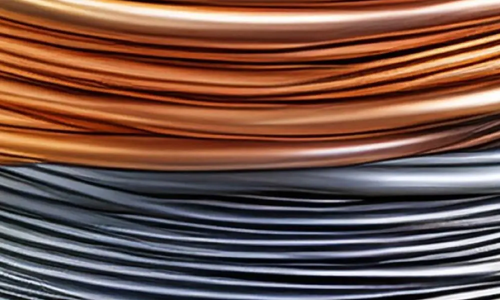
The most common conductive materials are copper and aluminum
2.1 Conductor materials
The conductor material —most commonly copper and aluminum—is the primary factor determining a cable’s current-carrying capacity. Copper conducts electricity better than aluminum, so for the same cross-sectional area, a copper-core cable can always carry a higher current than an aluminum-core cable. On the other hand, copper is significantly heavier and more expensive, making the choice of conductor material essentially a trade-off between operational performance and investment costs.
2.2 Insulating materials
While the conductor determines the "current-carrying capacity," the insulation layer determines the cable’s temperature rating. Each type of insulating material has its own temperature rating—that is, the maximum temperature at which the cable can operate continuously without aging or degrading in quality. For example, XLPE insulation can withstand significantly higher operating temperatures than PVC, so for the same conductor cross-sectional area, XLPE cable offers superior current-carrying capacity compared to PVC cable.
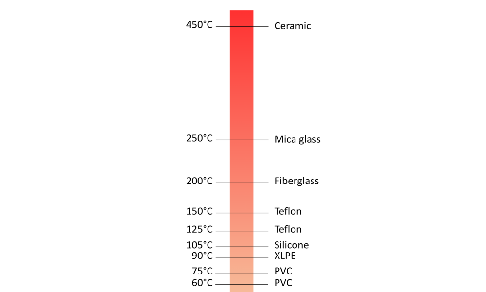
Common Temperature Ranges for Electrical Cables
2.3 Environment temperature
During operation, cables constantly dissipate heat into the surrounding environment—and the rate of heat dissipation depends heavily on the temperature where the cable is installed. The hotter the environment, the more difficult it is for the cable to dissipate heat, which in turn narrows the actual allowable current. A cable installed in a hot machine room or near industrial equipment that generates significant heat will therefore only be safe at a current level much lower than when installed in a temperature-controlled space.
2.4 Installation method
The way a cable is installed—whether it runs exposed in the open, is routed through underground conduit, or is embedded in a wall—also plays a decisive role in the cable’s heat dissipation capability. Cables in direct contact with the air always dissipate heat more effectively than those enclosed in insulation or tightly packed in narrow conduits. For this reason, in installation configurations that limit heat dissipation, engineers must apply a derating factor to the allowable current rating to ensure the cable always operates within safe limits.
The installation methods described in HELU's technical documentation include:
- A1 — Installation in electrical conduit, concealed within an insulated wall (single-core cable): Single cores in electrical installation tubing in an insulated wall
- A2 — Installation in electrical conduits, embedded in insulated walls (multi-core cable/sheathed cable): Multi-core cable or multicore, sheathed cable in an electrical installation tube in an insulated wall
- B1 — Installed in electrical conduit, surface-mounted on the wall (single-conductor wire): Single cores in electrical
installation tubing on a wall - B2 — Installation in electrical conduit, surface-mounted on the wall (multi-conductor cable/sheathed cable): Same as B1, but using multi-conductor cable or sheathed cable installed in conduit mounted on the wall.
- C — Direct wall installation: Single-core or multi-core cables (or sheathed cables) are mounted directly against the wall surface, with no gap.
- E — Outdoor/exposed installation, with clearance from the wall (Installation in the open): Multi-conductor cables or sheathed cables must be installed at a minimum distance from the wall equal to 0.3 times the cable’s outer diameter (≥ 0.3 × d).
- F — Single-core cables installed outdoors, with a spacing of ≥ 1×d, where the cores are in contact: Applies to single-core cables (typically three cores forming a single circuit) installed at a minimum distance of one outer diameter (≥ 1 × d) from the wall, but where the individual cores are placed close together or in contact with one another.
- G — Single-core cable for outdoor installation, with a spacing of ≥ 1×d, and the cores spaced apart (with spacing d): Similar to F, but the individual cores are spaced apart by a distance d (equal to the outer diameter of each core), allowing air to circulate between the cores.
3. What is a current-carrying capacity table used for?
The current carrying capacities of cables and wires are listed in current carrying capacity tables by type and installation method. These tables for cable cross-sections are based on applicable standards and assist in selecting the right cables for your application.
In HELU's technical documentation, you can find specifications regarding the allowable current for various types of cables, such as:
3.1 Current carrying capacity table by installation method
The following table provides information on the permissible current for installation methods A1, A2, B1, and B2. For other methods, please refer to our Technical Documentation, pages 6 through 21 .
| Model abbreviations | H07V2-K H07Z-U, -R, -K | N2XY, N2X2Y N2XH, N2XCH (N)HXH-FE180 (N)HXCH-FE180 | H07V2-K H07Z-U, -R, -K | N2XY, N2X2Y N2XH, N2XCH (N)HXH-FE180 (N)HXCH-FE180 | ||||
| A1 | A2 | B1 | B2 | |||||
| Number of loaded cores | 2 | 3 | 2 | 3 | 2 | 3 | 2 | 3 |
| Cable cross-sectional area (mm²) | ||||||||
| 1.5 | 19.0 | 17.0 | 18.5 | 16.5 | 23.0 | 20.0 | 22.0 | 19.5 |
| 2.5 | 26.0 | 23.0 | 25.0 | 22.0 | 31.0 | 28.0 | 30.0 | 26.0 |
| 4 | 35.0 | 31.0 | 33.0 | 30.0 | 42.0 | 37.0 | 40.0 | 35.0 |
| 6 | 45.0 | 40.0 | 42.0 | 38.0 | 54.0 | 48.0 | 51.0 | 44.0 |
| 10 | 61.0 | 54.0 | 57.0 | 51.0 | 75.0 | 66.0 | 69.0 | 60.0 |
3.2 Current carrying capacity table for aluminum conductors
The following table provides information on the allowable current ratings for certain types of 0.6/1 kV aluminum cables, such as NYY, NAYY, NYCY, NYCWY, and NAYCWY. For more detailed information, please refer to our Technical Documentation, pages 15 through 21 .
Rated current (A), underground installation (20°C), in accordance with DIN VDE 0276 Part 603, duty cycle factor 0.72
| Cable cross-sectional area (mm²) | NAYY | NAYCY | NAYCWY |
| 16 | - | - | - |
| 25 | 102 - 160 | 108 | 103 |
| 35 | 123–193 | 129 | 123 |
| 50 | 144 - 230 | 153 | 145 |
Rated current (A), outdoor/overhead installation (30°C)
| Cable cross-sectional area (mm²) | NAYY | NAYCY | NAYCWY |
| 16 | - | - | - |
| 25 | 82–110 | 91 | 83 |
| 35 | 100 - 135 | 112 | 101 |
| 50 | 119 - 166 | 137 | 121 |
3.3 Current carrying capacity table for silicone-insulated cables
Specifications for the allowable current in silicone-insulated cables are divided into three groups:
- Group 1: One or more single-core wires installed in a conduit.
- Group 2: Multi-conductor cables, sheathed cables, and flexible cables installed in open conduits or ventilated conduits.
- Group 3: Single-core cables installed outdoors (exposed), in which the cables are spaced apart by a minimum distance equal to the diameter of the cable itself.
For more details, please refer to our Technical Documentation, page 14 .
3.4 Current carrying capacity table for XLPE-insulated medium-voltage cables
Includes specifications for medium-voltage cable lines rated at 6/10 kV, 12/20 kV, and 18/30 kV with copper and aluminum conductors, such as N2XSY, NA2XSY, N2XS2Y, NA2XS2Y, N2XS(F)2Y, NA2XS(F)2Y, N2XS(FL)2Y, and NA2XS(FL)2Y
For more details, please refer to our Technical Documentation, page 21 .
4. How to determine conductor cross sections
4.1 Step 1: Use the current carrying capacity table
Use the current-carrying capacity table to find the cable type and corresponding installation method that you need. Then select a conductor cross-section that exhibits an equal or greater current carrying capacity than the operating current in your application.
4.2 Step 2: Apply derating factors
Derating factors that are not already included in in the current-carrying capacity table must be factored in when determining the conductor cross-section. You can find tips on how to do this and more in our technical tables (starting on page 17).
Conversion factors for different environmental remperatures
| Permissible operating temperature | 60°C | 70°C | 80°C | 85°C | 90°C |
| Ambient Temperature (°C) | |||||
| 30 | 1.00 | 1.00 | 1.00 | 1.00 | 1.00 |
| 40 | 0.82 | 0.87 | 0.89 | 0.90 | 0.91 |
| 55 | 0.41 | 0.61 | 0.71 | - | 0.76 |
| 60 | - | 0.50 | 0.63 | - | 0.71 |
| 70 | - | - | 0.45 | - | 0.58 |
| 80 | - | - | - | - | 0.41 |
Conversion factors for heat-resistant cables
| Permissible operating temperature | 80°C | 90°C | 110°C | 135°C | 180°C |
| Ambient Temperature (°C) | |||||
| Up to 50 | 1.00 | 1.00 | 1.00 | 1.00 | 1.00 |
| 55 | 0.91 | 0.91 | 1.00 | 1.00 | 1.00 |
| 70 | 0.58 | 0.74 | 1.00 | 1.00 | 1.00 |
| 80 | - | 0.50 | 1.00 | 1.00 | 1.00 |
| 105 | - | - | 0.41 | 0.87 | 1.00 |
| 130 | - | - | - | 0.35 | 1.00 |
| 175 | - | - | - | - | 0.41 |
Conclusion: Safety Through Good Planning
Selecting the right conductor cross-section is paramount for ensuring the safe and efficient operation of electrical systems. Calculating too small of a conductor cross-section risks overheating, damage, and fire.
HELU is always ready to help you choose the right type of cable for your application. In our Technical Reference Guide , you’ll find comprehensive tables of allowable current ratings, correction factors, and other technical information presented in an easy-to-understand format. Contact our team of experts for personalized advice!
Contact our HELU Vietnam engineers to get a quote & expert consultation
Deepen your knowledge with our FAQ series
- What is the level of protection provided by an enclosure? How do you interpret the IP code?
- The Significance of VDE Certification for Electrical Cables
- Why is it so important for cables and wires to not only be fire-resistant but also halogen-free?
- The Meaning of the UL and TC-ER Markings on Electrical Cables
- In the world of Ethernet, what does “Cat” stand for?
- What’s Behind the Name “Incoterms”?
- What is the average lifespan of a control cable?
- What is the difference between a cable and an electrical wire?
- Copper vs. Aluminum: How to Choose the Right Type of Conductor?
- How many types of brass cable clamps are there?