What is fiber optic cable attenuation? Causes, allowable levels & how to measure it
Attenuation is one of the important parameters used to evaluate the quality of a fiber optic cable link. Excessive attenuation can reduce the transmission distance, affect signal quality, and impact system stability. So, what factors affect attenuation, what level is considered appropriate, and how is it measured?
1. What is fiber optic cable attenuation?
Fiber optic cable attenuation is the gradual reduction in the power of an optical signal as it travels through an optical fiber. As the fiber optic transmission path becomes longer, the signal has to travel a greater distance, and the level of signal reduction tends to increase accordingly. This parameter is commonly expressed in decibels per kilometer (dB/km), also known as the attenuation coefficient or attenuation rate of the optical fiber.
2. How does fiber optic cable attenuation affect the system?
The attenuation level determines how far an optical signal can travel and how well its quality can be maintained when it reaches the receiving device. When the loss is too high, the signal power may fall to a level at which the receiver has difficulty accurately detecting the data, thereby reducing performance and affecting overall system stability.
During the design of a fiber optic network , attenuation is a parameter that needs to be considered from the beginning because it is directly related to several technical factors, including:
- Maximum transmission distance: The higher the attenuation, the more limited the distance over which the signal can be transmitted effectively.
- Optical link budget calculation: The total loss of the link needs to remain within the power limits that the system can support.
- Receiver sensitivity: The signal power reaching the receiver must be sufficiently high for the device to accurately receive and process data.
- Bit Error Rate (BER): High attenuation can weaken the signal, thereby increasing the risk of errors during data transmission.
- Network reliability: Controlling attenuation helps maintain a stable transmission link under normal operating conditions as well as when unfavorable variations occur.
If the attenuation level exceeds the allowable limit, the system may experience issues such as an increased bit error rate, reduced data transmission speed, intermittent connectivity, or service interruptions. In some cases, corrective measures may also require additional equipment or infrastructure adjustments to ensure that the signal maintains sufficient power.
3. The 3 main causes of fiber optic cable attenuation
There are several causes of fiber optic cable attenuation, with three of the most common being:
3.1. Attenuation due to absorption
Absorption occurs when unwanted components in the optical fiber material absorb light energy. Certain impurities, such as metal particles or moisture, can increase absorption at specific wavelengths. The optical energy is then converted into heat, reducing the signal power as it travels through the fiber.
Some notable factors include:
| Factor | Effect on attenuation |
| Impurities in the material | Metal particles or unwanted components in the optical fiber can absorb light more strongly at certain wavelengths, reducing signal power. |
| Moisture and “water peak” | Moisture can increase attenuation around the 1385 nm wavelength region, creating a higher-loss region and limiting the use of certain wavelengths in traditional optical fibers. |
Modern manufacturing technologies help reduce the effects of moisture, allowing optical fibers to operate more effectively in wavelength regions previously affected by the water peak. By reducing attenuation caused by moisture, the range of usable wavelengths can be expanded, providing additional transmission capacity for CWDM (Coarse Wavelength Division Multiplexing) systems.
3.2. Attenuation due to scattering
As light travels along an optical fiber, part of its energy does not continue in the main direction of transmission but is scattered in different directions. This phenomenon is commonly known as Rayleigh scattering. Some of the scattered light may escape from the core, while another portion is reflected back toward the light source.
At the material level, scattering originates from very small variations in the composition and density of the optical glass:
| Factor | Effect on attenuation |
| Microscopic variations in the glass material | Create inherent scattering |
| Higher dopant concentration | Can increase scattering and attenuation |
| Multimode fiber | Typically has a higher dopant concentration, so its attenuation is generally higher than that of Single Mode fiber |
3.3. Attenuation due to bending
Unlike scattering and absorption, bending loss can occur during the installation, routing, or operation of fiber optic cables. When the fiber is deformed or bent with a radius that is too small, the path of the light is affected, and part of the energy may escape from the core.
Bending loss is generally divided into two types:
| Type of attenuation | Characteristics | Common causes |
| Microbending | Very small deformations along the optical fiber that are difficult to identify visually | Fiber being compressed, pinched, or subjected to pressure |
| Macrobending | The fiber is bent into a clearly visible curve with a small radius | Excessive bending or failure to maintain the required bend radius |
Other causes:
In addition to scattering, absorption, and bending, which are the three main attenuation mechanisms, fiber optic cables can also be affected by various other factors during manufacturing, installation, and operation. Fiber quality, splices, connectors, mechanical impacts, and environmental conditions can all increase attenuation and affect transmission quality.
4. Fiber optic cable attenuation levels & how to calculate total attenuation
The following are typical attenuation levels for optical fibers and some commonly encountered connection points in practice.
4.1. Attenuation levels of Multimode and Single Mode fiber optic cables
The attenuation of a fiber optic cable is not fixed and varies depending on the fiber type and operating wavelength. The following table illustrates typical attenuation values at commonly used optical fiber wavelengths:
| Fiber type | Operating wavelength | Typical attenuation |
| Multimode fiber optic cable | 850 nm | 3 dB/km |
| Multimode fiber optic cable | 1300 nm | 1 dB/km |
| Single Mode fiber optic cable | 1310 nm | 0.4 dB/km |
| Single Mode fiber optic cable | 1550 nm | 0.25 dB/km |
The typical attenuation levels show that 1310 nm and 1550 nm are commonly preferred for long-distance transmission systems because they have lower attenuation than Multimode systems operating at shorter wavelengths.
4.2. Attenuation at connection points
In addition to the inherent attenuation of the optical fiber, the total attenuation of a link also includes losses occurring at splices, connectors, and other connection points. The following values are typical reference levels commonly used in the design and evaluation of optical links:
| Component | Type | Reference attenuation |
| Optical splice | Fusion splice | 0.1–0.2 dB/splice |
| Optical splice | Mechanical splice | 0.3 dB/splice |
| Optical connector | Adhesive-polished connector | 0.3–0.5 dB/connector |
| Optical connector | Pre-polished splice connector | 0.75 dB/connector |
When calculating the total attenuation of a fiber optic cable link, you need to include the attenuation of the fiber, splices, connectors, and other passive components along the transmission path. To estimate the total loss of a cable system, the following formula can be used:
| (0.5 dB × number of connectors) + (0.2 dB × number of splices) + fiber attenuation over the entire cable length |
Note: The above values should be considered reference values rather than universally applicable limits for all systems. When accepting or designing a specific link, priority should be given to the attenuation specifications provided by component manufacturers and the technical standards applicable to the system.
5. Standards and methods for measuring fiber optic cable attenuation
To ensure accurate and consistent evaluation results, fiber attenuation measurements are carried out using standardized methods. IEC 60793-1-40 – Optical fibres – Part 1-40: Attenuation measurement methods is an international standard that specifies requirements and measurement methods for Single Mode and Multimode optical fibers. The current edition was published by IEC in 2024, replacing the 2019 edition.
For attenuation measurement, IEC 60793-1-40 currently specifies four main methods:
| Method | Method name | Applicable fiber type |
| Method A | Cut-back | Multimode and Single Mode fiber |
| Method B | Insertion loss | Multimode and Single Mode fiber |
| Method C | Backscattering | Multimode and Single Mode fiber |
| Method D | Modelling spectral attenuation | Single Mode fiber |
In Vietnam, relevant national standards for optical fiber cables and optical communication systems may be developed based on or reference corresponding IEC standards. When selecting the applicable standard for a specific product or system, the current TCVN standard, fiber type, and system technical requirements should be checked accordingly.
6. Fiber optic cable attenuation measurement in practice
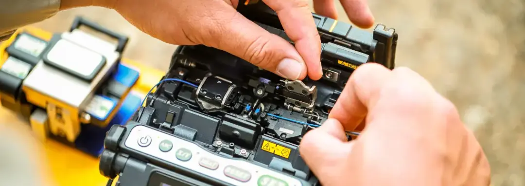
Attenuation can be measured using specialized instruments depending on the purpose of the test. The most commonly used instruments are currently the Optical Power Meter (OPM) and Optical Time Domain Reflectometer (OTDR).
6.1. Optical Power Meter (OPM)
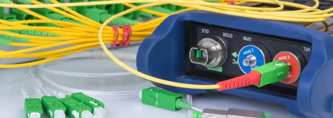
An OPM (Optical Power Meter) determines attenuation based on the difference in optical power during the measurement. Under IEC 60793-1-40, this equipment can be used for Method A – Cut-back and Method B – Insertion Loss, depending on the configuration and measurement purpose. With a properly calibrated light source and measurement instrument, an Optical Power Meter can be used to evaluate the attenuation of a fiber or an entire link.
| Measurement component | Purpose | Application |
| Light source + Power Meter | Determine total link attenuation | Field testing and acceptance testing |
| Loopback configuration | Evaluate attenuation in both directions | Data Center link testing |
| Reference cable | Establish the reference level before measurement | Laboratory and field testing |
The measurement results should be compared with the expected attenuation level in the design. To avoid measurement errors, ensure that the equipment is calibrated, connectors are clean, and connection points are properly aligned.
6.2. Optical Time Domain Reflectometer (OTDR)
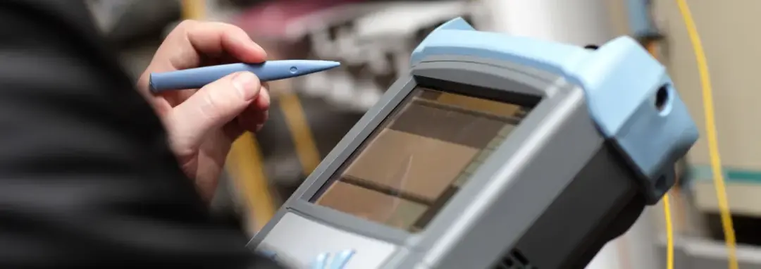
An OTDR (Optical Time Domain Reflectometer) operates by sending light pulses into the optical fiber and analyzing the backscattered and reflected signals. This measurement method generally corresponds to Method C – Backscattering, allowing attenuation to be evaluated along the length of the link and the locations of loss points, splices, connectors, or other abnormalities to be identified.
| OTDR information | Inspection value |
| Backscatter Trace | Evaluate the attenuation trend along the fiber length |
| Event Markers | Identify the locations of connectors, splices, or abnormal points |
| Reflectance Peaks | Evaluate reflection points |
| Dead Zones | Identify the limits of the areas that can be measured accurately |
OTDR is particularly useful for troubleshooting or inspecting installed fiber optic links, helping technicians identify potential causes such as poor splices, connector issues, or fiber bending.
7. How to reduce fiber optic cable attenuation in practice
Attenuation control measures should be selected based on the cause of attenuation, the signal type, and the characteristics of the transmission system. Some common approaches include:
- Increase signal power: A higher-power transmitter, amplifier, or repeater can be used to compensate for the power reduction along the transmission path.
- Select an appropriate wavelength: Attenuation characteristics vary by wavelength, so selecting a suitable wavelength range can help reduce the effects of absorption and scattering.
- Use high-quality and suitable fiber optic cables: Materials with high purity and uniformity help minimize attenuation caused by the characteristics of the transmission medium. Selecting a suitable fiber optic cable is also particularly important for long-distance transmission links.
- Limit factors that affect the signal: Control environmental impacts and apply appropriate protection, filtering, or signal processing measures for each system.
- Optimize the transmission path: Proper transmission path design, control of the link length, and appropriate cable routing can help minimize unnecessary losses and maintain sufficient signal quality at the receiving device.
8. HELU fiber optic cables – Reliable, high-quality transmission solutions
Effective attenuation control starts with selecting a fiber optic cable that is suitable for the characteristics of the transmission link and the installation environment. In addition to the attenuation specifications of the optical fiber, cable construction, fiber protection, and durability in the operating environment should also be considered to maintain signal quality over the long term.
With our HELUCOM® fiber optic cable portfolio, we HELU provide a range of solutions for transmission applications and industrial networks, from Single Mode and Multimode fiber optic cables to GOF, HCS, and POF solutions, as well as indoor, outdoor, and specialized fiber optic cables for industrial environments.
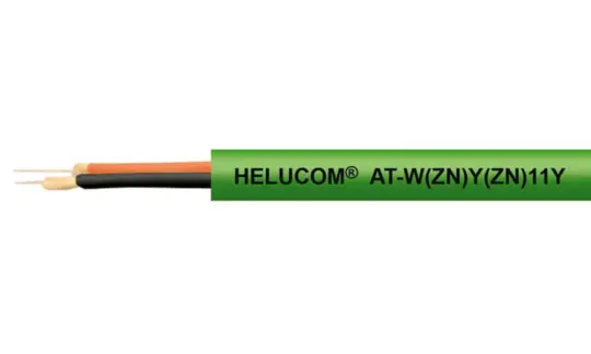
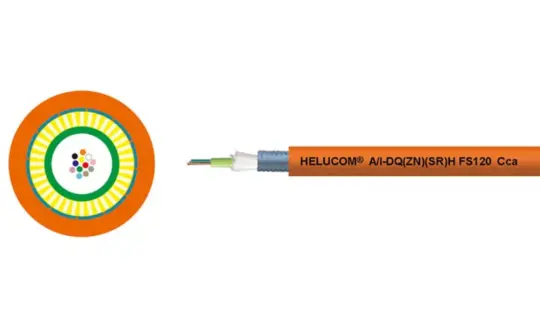
Some product types are designed for specific operating conditions. For example, HELUCOM® AT-W(ZN)Y(ZN)11Y uses OM2 Multimode fiber, GRP reinforcement and Aramid yarn, with a PUR jacket that provides oil resistance and UV resistance, making it suitable for industrial applications and cable drag chains. Meanwhile, HELUCOM® FS120 supports functional integrity under fire conditions according to IEC 60331-25 and features a water-resistant, UV-resistant, halogen-free construction.
If you are looking for fiber optic cables that meet your system's technical requirements, feel free to contact our HELU Vietnam team for advice on the appropriate cable type, construction, and solution for your specific application.