How to crimp an Ethernet LAN cable correctly: Color code & wiring
Crimping an Ethernet LAN cable becomes much easier when you understand the rules for arranging the 8 wires and the RJ45 wiring standards. This article provides a step-by-step guide, from preparing the necessary tools and identifying the T568A or T568B standard to arranging the wire colors, crimping the RJ45 connector, and testing the cable after completion.
What do you need to crimp an Ethernet LAN cable?
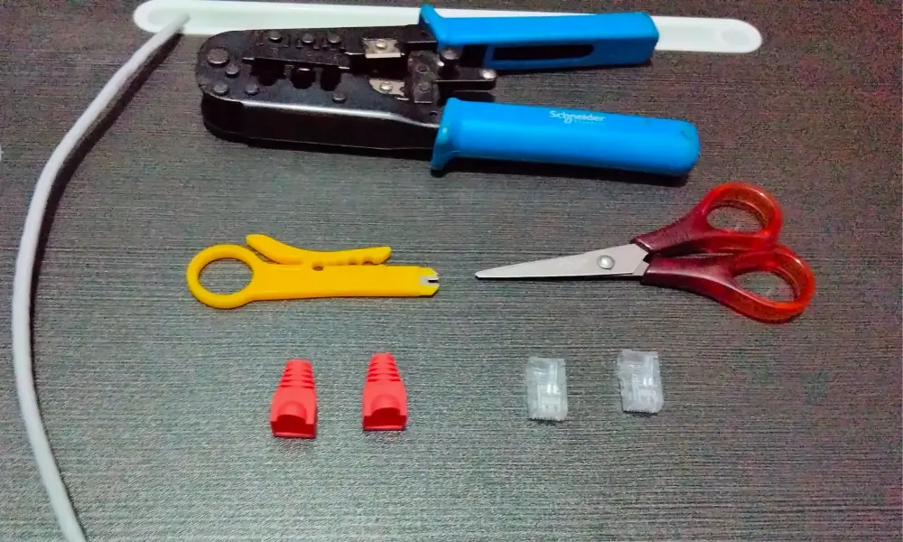
Before crimping an Ethernet cable, prepare all the necessary tools to ensure accurate work and a stable connection. The essential items include:
- Ethernet cables: Cat5e or Cat6 cables are commonly used and contain 8 internal wires. Choose a cable suitable for the required distance and application.
- RJ45 connectors: Used to connect the network cable to routers, switches, computers, and other network devices. Choose an RJ45 connector compatible with the type of cable.
- Crimping tool: Used to secure the wires into the RJ45 connector and create stable electrical contact.
- Wire stripper or cutter: Used to strip the cable outer sheath and trim the wires before crimping.
- Cable tester: Used to check the wire sequence and confirm that the cable has been correctly connected after crimping.
An RJ45 connector has 8 contact pins designed to connect with the 8 conductors of an Ethernet cable. Each wire is inserted into a corresponding position on the connector according to a defined wiring scheme. The RJ45 color code helps identify the twisted pairs and determine the position of each wire during termination. Following this convention creates consistency during cable crimping and makes network installation, testing, and maintenance easier.
Ethernet LAN cable wiring standards
When crimping an Ethernet LAN cable, T568A and T568B are two common wiring standards that define the order in which the 8 wires are arranged across the 8 pins of an RJ45 connector. Both can provide a stable Ethernet connection when terminated correctly. The main difference between the two standards is the position of the green and orange wire pairs.
T568A Standard
T568A is one of the two standards that defines the wire order when terminating an Ethernet cable with an RJ45 connector. This standard is used in some residential systems, government installations, and many international projects.
The pinout sequence for the T568A standard is as follows:
| Pin | Color code | Function |
| 1 | White/Green | Transmit data (+) |
| 2 | Green | Transmit data (-) |
| 3 | White/Orange | Receive data (+) |
| 4 | Blue | Used for Power over Ethernet (PoE) |
| 5 | White/Blue | Used for Power over Ethernet (PoE) |
| 6 | Orange | Receive data (-) |
| 7 | White/Brown | Used for Power over Ethernet (PoE) |
| 8 | Brown | Used for Power over Ethernet (PoE) |
The T568A standard is suitable when:
- The existing system uses T568A and needs to be expanded or have cables replaced.
- The project requires compliance with a specific wiring standard.
- Compatibility with certain legacy telecommunications infrastructure needs to be maintained.
- Deploying international projects or projects in regions where T568A is commonly used, such as Europe and the Pacific region.
T568B Standard
T568B is an RJ45 wiring standard with a structure similar to T568A, but it swaps the positions of the green and orange wire pairs. It is commonly used in many commercial and enterprise network systems.
The pinout sequence for the T568B standard is as follows:
| Pin | Color code | Function |
| 1 | White/Orange | Transmit data (+) |
| 2 | Orange | Transmit data (-) |
| 3 | White/Green | Receive data (+) |
| 4 | Blue | Used for Power over Ethernet (PoE) |
| 5 | White/Blue | Used for Power over Ethernet (PoE) |
| 6 | Green | Receive data (-) |
| 7 | White/Brown | Used for Power over Ethernet (PoE) |
| 8 | Brown | Used for Power over Ethernet (PoE) |
T568B is suitable when:
- Installing a new network system where there is no specific requirement to use T568A.
- Deploying commercial, office, or enterprise networks.
- Expanding an existing system that uses T568B.
- Maintaining consistency with the existing cabling and network equipment.
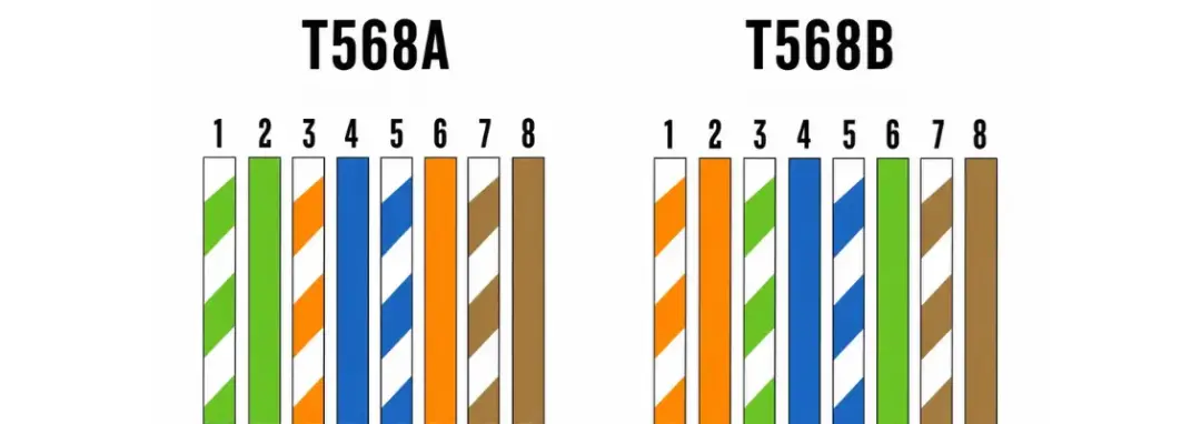
Comparison of T568A and T568B standards.
| Criteria | T568A | T568B |
| Wire pair arrangement | Green pair on pins 1 – 2, orange pair on pins 3 – 6 | Orange pair on pins 1 – 2, green pair on pins 3 – 6 |
| Popularity | Commonly used for certain specific requirements or legacy systems | Common in modern enterprise and commercial network systems |
| Speed & performance | Equivalent to T568B when correctly terminated | Equivalent to T568A when correctly terminated |
| When to choose | When compatibility with an existing T568A system or project requirements is needed | For new installations or existing systems using T568B |
Neither standard inherently provides higher network speed or performance. T568A and T568B can deliver equivalent performance when terminated correctly. Therefore, when choosing between them, prioritize the standard already used in the system to ensure consistency.
Why should Ethernet LAN cables be crimped according to a standard?
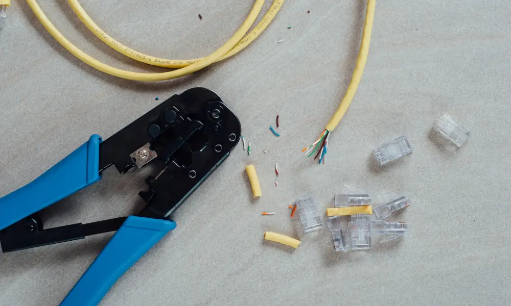
Crimping an Ethernet LAN cable according to the correct standard not only allows the cable to connect properly to network devices but also ensures connection stability and efficient data transmission. Key benefits include:
- Ensure accurate connections: Arranging the wires correctly according to T568A or T568B allows the RJ45 pins to make proper contact with the conductors, reducing connection failures or intermittent signals.
- Maintain data transmission quality: Correct wiring helps minimize signal errors and ensures that the cable operates reliably as designed.
- Control cable length: Crimping cables yourself allows you to adjust the cable length to suit each installation location, avoiding excess or insufficient cable, especially when routing cables inside network cabinets or confined spaces.
- Reduce costs: For systems requiring many network cables, purchasing cable in bulk along with RJ45 connectors and crimping them yourself can be more cost-effective than relying entirely on pre-made cables.
- Simplify testing and maintenance: Applying a consistent wiring standard makes it easier to identify faults, replace cables, or expand the network system.
Straight-through and crossover Ethernet LAN cable configurations
The way the wires are arranged at both ends of an RJ45 cable determines whether it is a straight-through cable or a crossover cable. These two types differ in their wiring configurations and are used for different types of device connections.
| Cable type | Wiring at both ends | Common application |
| Straight-through cable | T568A - T568A or T568B - T568B | Connecting different types of devices |
| Crossover cable | T568A - T568B | Directly connecting similar devices |
Straight-through cable
A straight-through cable uses the same wiring standard at both ends, such as T568A - T568A or T568B - T568B. The corresponding pins at both ends remain in the same positions, making this configuration suitable for connecting different types of devices, such as a computer to a router or a computer to a switch. This is the most common cable configuration in standard network systems.
Crossover cable
A crossover cable uses two different wiring standards at each end: one end uses T568A and the other uses T568B. This wiring configuration reverses the positions of the transmit and receive pairs, making it suitable for directly connecting certain similar devices, such as a computer to a computer or a switch to a switch, without an intermediary device such as a router.
However, many modern network devices support Auto MDI-X, which automatically detects and adjusts the connection. As a result, crossover cables are less commonly used today and are generally only required for older devices that do not support this feature.
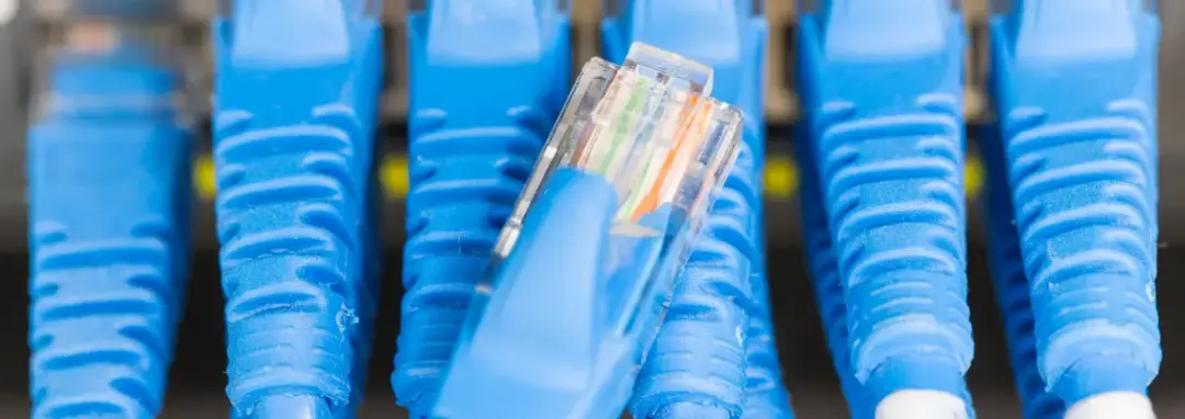
How to crimp an 8-wire Ethernet LAN cable?
After preparing all the necessary tools, you can follow the steps below to crimp the cable. This guide applies to a straight-through Ethernet LAN cable using the T568B standard at both ends.
Step 1: Strip the cable outer sheath
Use a wire stripper to remove approximately 2 – 3 cm of the outer sheath at the end of the cable, exposing the internal wires. Work carefully to avoid scratching or damaging the conductors.
Step 2: Separate and straighten the 8 wires
After removing the outer sheath, you will see 4 twisted pairs, consisting of 8 wires in total. Separate the pairs and straighten each wire as much as possible to make them easier to arrange.
Step 3: Arrange the 8 wires according to the T568B Standard
Arrange the 8 wires in a single row according to the following order from pin 1 to pin 8: White/Orange → Orange → White/Green → Blue → White/Blue → Green → White/Brown → Brown. Keep the wires close together and in the correct order throughout the preparation process to prevent them from being rearranged accidentally.
Step 4: Trim the 8 wires evenly
Hold the 8 wires firmly and use a cutter to trim their ends evenly. The stripped wire length should be sufficient to fit into the RJ45 connector. Do not leave the wires too long, as the outer sheath may not be secured properly inside the RJ45 connector. Conversely, if the wires are too short, the conductors may not reach the contact pins inside the connector.
Step 5: Insert the 8 wires into the RJ45 connector
Hold the RJ45 connector with the metal contact pins facing upward and the locking tab facing away from you, then insert the 8 wires into the connector in the correct order. Push the wires in until the ends of all 8 wires reach the end of the RJ45 connector. At the same time, the outer sheath should extend far enough into the connector to be secured during crimping.
Step 6: Use the crimping tool to secure the RJ45 connector
Place the RJ45 connector into the correct 8P slot on the crimping tool. Squeeze the tool firmly until the crimping process is complete. The crimping force presses the metal contact pins into the conductors while also securing the outer sheath, reducing direct stress on the wires when the cable is pulled or moved.
Step 7: Check the connector and crimp the other end
After crimping, inspect the RJ45 connector:
- The contact pins should be pressed down evenly.
- The 8 wires should remain in the correct order.
- All wires should extend fully into the connector.
- The cable outer sheath should be securely held inside the RJ45 connector.
Then repeat the same process for the other end. For a T568B straight-through cable, both ends must use the same T568B color sequence.
Step 8: Test the Ethernet cable after crimping
Finally, use a cable tester to check the continuity of all 8 wires. Connect both ends of the cable to the tester and check the signals for pins 1 – 8. If the signals appear in the correct order at both ends, the cable has been terminated correctly. If one or more pins do not light up or the signal sequence is incorrect, check the RJ45 connector and re-crimp the cable.
Note: If you want to crimp a crossover cable, the wiring at the two ends will be different: one end uses T568A and the other uses T568B. Therefore, determine the type of cable required before starting the crimping process.
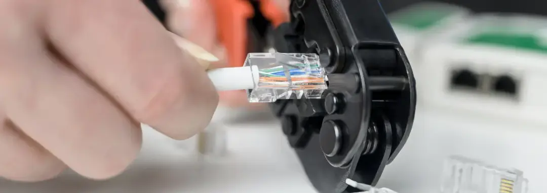
How to troubleshoot common Ethernet LAN cable crimping issues?
If an Ethernet LAN cable does not work as expected after crimping, a cable tester can help determine whether the problem lies with the conductors or the connector. Based on the signal displayed by the tester, you can identify the likely cause and choose an appropriate solution instead of re-crimping the entire cable.
| Symptom | Common cause | Solution |
| Tester shows Open (one or more pins do not light up) | Wire not fully inserted, poor contact, or broken conductor | Re-crimp the RJ45 connector; inspect the wire and replace the connector if necessary |
| Tester shows Miswire (incorrect wire order) | Wires arranged incorrectly at one end | Cut off the cable end and re-terminate according to T568A/T568B |
| Tester shows Short | Wires touching each other or damaged cable | Re-terminate the connector; inspect and replace the cable if necessary |
| RJ45 connector is loose or easily pulls off | The cable outer sheath is not secured or insufficient crimping force | Re-crimp and ensure the cable outer sheath is properly held inside the RJ45 connector |
| Intermittent connection | Poor contact, loose crimp, or damaged conductor | Re-crimp the RJ45 connector; replace the cable if damaged |
Some tips for crimping Ethernet LAN cables
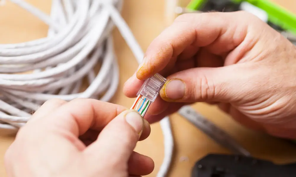
To ensure accurate cable crimping and make future testing and maintenance easier, keep the following points in mind:
- Use a consistent wiring standard: Choose T568A or T568B from the beginning and maintain the same standard throughout the system.
- Choose a compatible RJ45 connector: Make sure the connector is suitable for the type of cable and conductor size being used.
- Double-check before crimping: Compare the 8-wire sequence with the T568A or T568B wiring diagram before inserting the wires into the RJ45 connector. This helps ensure the correct arrangement and prevent wiring errors.
- Use appropriate tools: Choose a good-quality crimping tool and cable tester to ensure secure connections and make it easier to identify faults.
- Crimp the connector firmly: Make sure the contact pins are pressed securely, while avoiding excessive force.
- Label the cables after completion: Mark the location, connected device, or purpose of each cable to make network management and maintenance easier, especially in systems with a large number of cables.
With extensive experience in cables and connectivity solutions, we HELU Vietnam provide a wide range of Ethernet LAN cable solutions to meet networking requirements across offices, buildings, and industrial environments. Our product portfolio includes Cat 5, Cat 6, Cat 7, and pre-terminated network cables, allowing businesses to choose the right solution based on data transmission requirements, installation environment, and deployment needs.
Don’t hesitate to contact us for expert advice and to find the right Ethernet LAN cable solution for your system!