M12 connector guide: Coding, Pinout & How to Choose
An M12 connector is a circular connector with a 12 mm threaded locking mechanism, standardized under the IEC 61076-2 series. It is an industrial cable connector used to connect sensors, actuators, industrial Ethernet networks and power supplies in dusty, wet and high-vibration environments. Each M12 connector type is identified by its coding (A, B, D, X and others). This guide explains how to read an M12 connector: which coding is used for what, when to replace RJ45 with M12, and 6 steps to choose the right M12 connector from the start.

Article Content
1. What is an M12 connector?
1.1 What does "M12" mean?
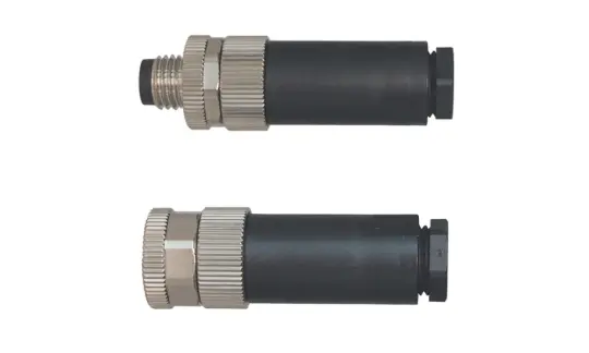
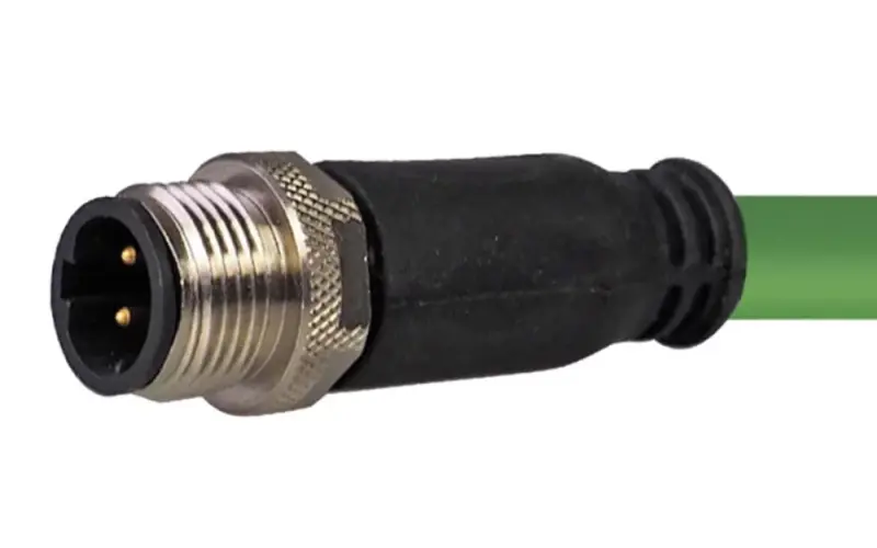
The M12 connector, also known as the M12 circular connector or M12 sensor connector, is a metric-system circular electrical cable connector with a 12-mm-diameter locking thread. The threaded locking mechanism creates a secure connection that will not work loose, which makes M12 ideal for applications that require high reliability.
The number after the "M" is the outer diameter of the locking thread in millimeters. M12 is the most common size in factory automation: small enough to fit on a sensor, yet large enough to hold up to 17 pins or carry up to 16 A. The same family also includes M5, M8, M16 and M23 connectors.
1.2 IEC standards for M12 connectors
The International Electrotechnical Commission (IEC) publishes the international standards for M12 connectors, grouped by application:
| Standards | Scope | Codings |
| IEC 61076-2-101 | Signals, sensors, fieldbus, 100 Mbit/s Ethernet | A, B, C, D, P |
| IEC 61076-2-109 | High-frequency data transmission up to 500 MHz | X, H |
| IEC 61076-2-111 | AC/DC power | E, F, K, L, M, S, T |
| IEC 61076-2-113 | Combined power and data up to 100 MHz | Y |
1.3 Key advantages of M12 cable connectors
The M12 connector has become a standard interface in industrial automation thanks to six key advantages:
- Reliable performance in harsh environments: M12 connectors are typically rated IP67 (dust-tight and protected against immersion in water up to 1 m for 30 minutes), with a common operating range of -40 °C to +85 °C. IP69K versions are available for high-pressure washdown areas.
- Vibration-resistant threaded locking: the two halves must be screwed together to connect. This design provides high mechanical strength and keeps the connection secure under vibration.
- International standardization: under IEC 61076-2, connectors with the same coding and pin count from different manufacturers can be mated, reducing dependence on a single supplier.
- One standard for many needs: M12 offers more than 10 coding types. The same connector size can carry sensor signals, Ethernet up to 10 Gbit/s or power up to 16 A.
- Compact, high-density design: an outer diameter of about 20 mm allows many ports on a single I/O box or on a small sensor housing.
- Good EMC protection: shielded M12 versions help keep signals stable near drives and motors.
2. M12 Connector structure
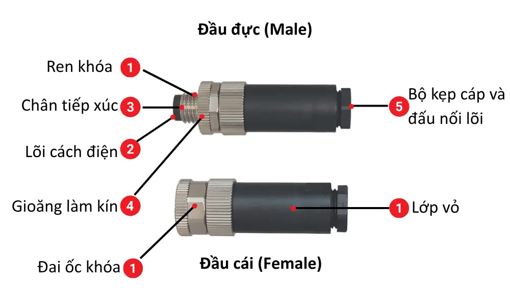
An M12 connector consists of five main components.
- Housing and coupling nut
- Insert
- Contact
- Seal
- Cable clamp and terminals
Each part uses a specific material for its role: mechanical strength, conductivity, insulation or sealing.
| Component | Typical materials | Function |
| Housing and coupling nut | Engineering plastic (PA) or metal (nickel-plated brass, stainless steel) | Provides mechanical strength and carries the M12×1 locking thread. Metal housings also provide EMI shielding |
| Insert | Engineering plastic | Holds and insulates the contacts. Carries the coding keyway (A, B, D, X…) so the connector can only be mated in the correct orientation and with the correct type |
| Contacts | Copper alloy, gold-plated | Male connectors have pins, female connectors have sockets. Gold plating prevents oxidation and keeps contact resistance low and stable |
| Seals | Rubber (O-rings, flat gaskets) | Keep dust and water out at the mating face and cable entry. Required for IP67 once the connector is fully tightened |
| Cable clamp and terminals | Plastic or metal, screw terminals | Grips the cable jacket and relieves strain on the terminations. Each connector seals only within a specific cable diameter range |
3. M12 connector coding
Coding is the "language" of the M12 connector. It tells you whether the connector is used for signals, data or power , and it only allows connectors with the same coding to mate. Coding is the first parameter to define, even before the number of pins.
| Codings | Pins | Main applications |
| A | 2 - 17 | Sensors, actuators, DC power, IO-Link, CANopen, DeviceNet |
| B | 5 | Non-Ethernet fieldbus, commonly PROFIBUS and Interbus |
| C | 3–6 | AC power, motor connections |
| D | 4 | Industrial Ethernet up to 100 Mbit/s: PROFINET, EtherNet/IP |
| X | 8 | Ethernet up to 10 Gbit/s, supports PoE (Power over Ethernet) |
| Y | 6 and 8 | Hybrid connector combining power and 100 Mbit/s Ethernet in one housing, used for fieldbus and EtherCAT |
| K | 2–4 + PE | High-power AC connections for motors and drives |
| L | 2–4 (+FE) | DC power for I/O modules and decentralized drives |
| S | 2–3 + PE | AC power |
| T | 2–4 | DC power |
| M | 2–5 + PE | Three-phase AC power |
| P | 4 + PE | Mainly EtherCAT applications |
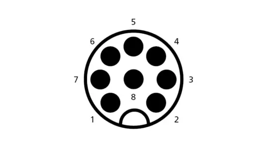
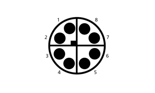
M12 ethernet connectors: D-Coded vs. X-Coded
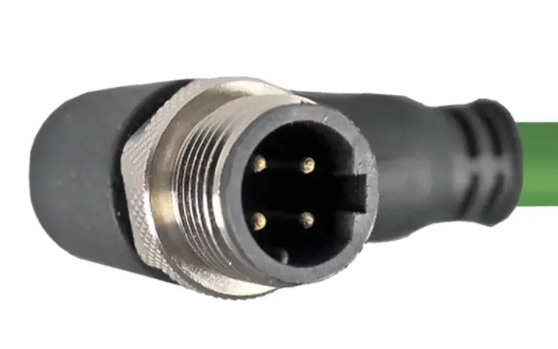
- D-coded M12 connectors have 4 pins, which means 2 wire pairs. 100BASE-TX uses only 2 pairs, so D-coding is sufficient for Fast Ethernet at 100 Mbit/s, the standard speed for PROFINET. D-coded connectors are typically used with cables up to Cat.5e and support PoE.
- X-coded M12 connectors have 8 pins, which means 4 wire pairs. Gigabit Ethernet requires all 4 pairs, and 10 Gbit/s requires Cat.6A cable. Inside an X-coded connector, a cross-shaped metal shield separates each wire pair to reduce crosstalk. This is why X-coding can reach 10 Gbit/s in the compact M12 size.
4. M12 connector pin count and pinout
A pinout is the "map" of a connector: it shows the position and number of each pin on the mating face. Each coding has its own pinout, so always compare the pinout of both the connector and the device before wiring. M12 connectors are available with 2 to 17 pins; the most common versions have 3, 4, 5, 8 and 12 pins. The pin count determines how many signals or power lines the connector can carry.
How to read an M12 pinout:
- Pinouts are usually drawn as viewed from the mating face. Male and female connectors are mirror images: pin 1 of a male connector is to the right of the keyway, while pin 1 of a female connector is to the left.
- The pins are arranged in a circle. 5-pin and 8-pin versions have an additional center pin (pin 5 and pin 8 respectively).
- A 3-pin A-coded connector uses pins 1, 3 and 4 and leaves pin 2 empty. This is why 3-pin sensors can usually be plugged into 4-pin or 5-pin A-coded ports.
4.1 M12 A-Coded 3-, 4- and 5-Pin pinout
| Pins | Wire color | Available on |
| 1 | Brown | 3, 4, 5 pins |
| 2 | White | 4 or 5 pins |
| 3 | Blue | 3, 4, 5 pins |
| 4 | Black | 3, 4, 5 pins |
| 5 | Gray (center pin) | 5 pins |
4.2 4-Pin M12 connector pinout (D-Coded, 10/100 Mbit/s Ethernet)
| Pin | Wire color | Signal |
| 1 | White–orange | Tx+ |
| 2 | White–green | Rx+ |
| 3 | Orange | Tx– |
| 4 | Green | Rx– |
The two wire pairs are arranged diagonally on the mating face: pair 1 uses pins 1 and 3 (transmit), and pair 2 uses pins 2 and 4 (receive). PROFINET cables use their own color code (yellow, white, orange and blue for pins 1, 2, 3 and 4), but the pin and signal assignment stays the same.
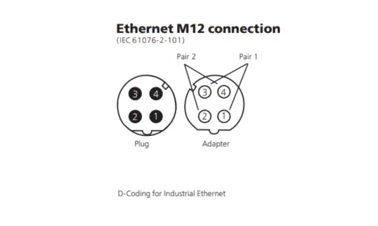
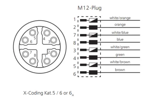
4.3 M12 X-coded 8-pin pinout (Cat.6A)
| Pin | Wire color |
| 1 | White–orange |
| 2 | Orange |
| 3 | White–green |
| 4 | Green |
| 5 | White–brown |
| 6 | Brown |
| 7 | White–blue |
| 8 | Blue |
On the X-coded mating face, the 8 pins are divided into 4 pairs (1–2, 3–4, 5–6 and 7–8). Each pair sits in one quadrant of the cross-shaped shield and corresponds to one twisted pair. On the RJ45 side, wire colors follow the T568B standard. X-coded connectors can be used with Cat.5, Cat.6 and Cat.6A cables.
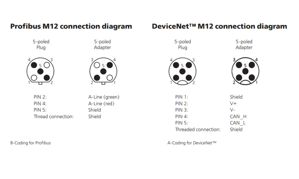
M12 Profibus and DeviceNet pinout diagram
Do you need a pinout diagram for an M12 A-coded 8-pin connector, PROFIBUS, DeviceNet, or M12 power code?
5. M12 connector types
M12 connectors are most commonly classified by coding and pin count. By mounting style, the most common types are:
5.1 Male vs. female M12 connectors
A male connector has pins, and a female connector has sockets. The common convention is that devices supplying power or signals (masters, switches, I/O modules) use female connectors, while receiving devices (sensors) use male connectors. For example, in IO-Link (IEC 61131-9), the master uses a female connector and the device uses a male connector.
5.2 Straight (180°) vs. right angle (90°) M12 connectors
Straight (180°) and right-angle (90°) are the two most common M12 connector designs. The main differences are:
| Straight (180°) | Right angle (90°) | |
| Cable exit | Parallel to the mating axis | Perpendicular to the mating axis |
| Advantages | Allows many ports side by side on a panel or I/O box. Easy to grip and tighten, convenient for frequent mating and unmating | Reduces installation depth. Routes the cable close to the equipment surface, avoids collisions with moving parts and prevents sharp cable bends behind the connector |
| Best for | Installations with enough space in front of the device: PLC cabinets, high-density I/O boxes | Limited height or side clearance: robot joints, flat devices, installations close to a wall |
6. Applications of M12 connectors

Thanks to their versatility, reliability and rugged design, M12 connectors are widely used across many industries:
- Industrial automation: connecting sensors, actuators and IO-Link devices.
- Industrial Ethernet: reliable connections for PROFINET, EtherNet/IP, EtherCAT and other networks.
- Fieldbus communication: PROFIBUS uses B-coded M12 connectors, while DeviceNet and CANopen use A-coded M12 connectors.
- Machine vision and robotics: high-bandwidth cameras use X-coded connectors. On robots and drag chains, the cable is usually the weak point, so continuous-flex or torsion-resistant cables are required.
- Food, beverage and pharmaceutical: areas cleaned with hot, high-pressure water require IP69K connectors (ISO 20653: 80 °C water jets at 80–100 bar).
- Renewable energy and marine: connecting sensors, monitoring and control equipment in wind turbines, solar power systems and ships.
- Transportation and automotive manufacturing: railway signaling, automotive assembly lines and automated guided vehicles (AGVs) in warehouses.
7. M12 vs. RJ45 connectors: Which one should you use?
Both M12 and RJ45 connectors can carry industrial Ethernet over the same cable categories (Cat.5 and above). However, M12 does not completely replace RJ45. The two connectors serve different areas of the same system, and the main difference is the installation environment:
| Criteria | RJ45 connectors | M12 circular connectors |
| Protection rating | IP20 for standard versions. Industrial versions (PushPull, ODVA) reach IP67 with an additional housing | IP67 as standard, some versions up to IP69K |
| Locking | Plastic latch that wears and loosens under vibration | Threaded coupling (or push-pull) that stays secure under vibration |
| Installation | Flat, allows many ports side by side, quick to plug and unplug | Requires space to tighten by hand |
| Component cost | Low, compatible with all IT equipment | Higher, but no external protective housing needed |
| Best location | Control cabinets, control rooms, switches, computers, service ports | Field level: sensors, cameras, robots, vibrating machinery |
In practice, many cable runs use both: the RJ45 end plugs into a switch in the cabinet, and the M12 end connects to a device in the field. This is why RJ45 to M12 cables are so common.
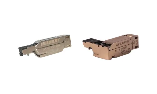
HELU offers RJ45 (IP20) to D-coded M12 (IP67) cables based on PROFInet Type A (fixed installation), Type B (flexible applications) and Type C (drag chain) cables, in lengths from 0.5 to 100 m.
Discover assembly instructions for RJ45 connectors and FastConnect cables
8. How to choose the right M12 connector: 6-step checklist
To select the appropriate M12 cable connector, you can refer to the following checklist:
- Determine the transmission type: select the coding type
· Sensors, IO-Link: code A; PROFIBUS: code B.
· 100 Mbit/s Ethernet: code D; 1–10 Gbit/s Ethernet: code X.
· AC power supply: code S or K; DC power supply: code T or L. - Determine the number of pins based on the number of signals to be transmitted: For a 3-wire sensor, use a 3-pin M12 connector. If there is a second signal, use a 4- or 5-pin connector.
- Match the connectors to the cables: The conductor size (AWG) and the cable outer diameter must be within the range accepted by the connector. For example, HELU connector 11024548 fits cables with an outer diameter of 4.0 - 6.0 mm, while cables with an outer diameter of 6.0 - 8.0 mm require part number 11024549. Outside this range, IP67 protection is no longer guaranteed.
- Assess the installation environment to select the IP rating and housing material:
· IP67 for most factories; IP69K for high-pressure washing areas.
· PA plastic for low-interference environments; nickel-plated brass when interference protection is required; stainless steel for corrosive environments (food, chemicals, coastal areas). - Select the installation type: straight or 90° angle, male or female end (see Section 5).
- Choose between on-site assembly or pre-assembled cable assemblies:opt for on-site assembly when precise lengths are required or for on-site repairs; choose pre-assembled cables when quick installation and consistent quality are needed.
9. M12 cable connectors and solutions from HELU
HELU offers a complete M8/M12 cable connector system , from sensors to Ethernet networks: cables, connectors, cable assemblies and tools. You do not need to combine cables and connectors from different suppliers and check compatibility yourself.
9.1 M8 / M12 A-coded circular connectors for sensors and actuators
These field-attachable connectors with screw terminals are designed for sensors, valves, indicator lights and I/O boxes. Two versions are available:
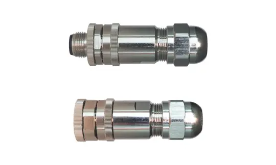
| Version | Size | Pins | Cable diameter | Type |
| PA66 GF25 plastic housing, unshielded, metal lock | M8 | 3, 4 | 3.5–4.8 mm | Male / female |
| PA66 GF25 plastic housing, unshielded, metal lock | M12 | 5, 8 | 4.0–6.0 mm or 6.0–8.0 mm | Male / female (8-pin: female) |
| Nickel-plated brass housing, shielded | M12 | 5, 8 | 4.0–6.0 mm or 6.0–8.0 mm | Male / female (8-pin: female) |
This series of connectors shares the following characteristics:
- Gold-plated contacts, IP67 protection rating.
- Operating temperature range: -40 °C to +85 °C.
- Threaded locking, compact design, quick on-site connection.
- Applications: intralogistics, AGVs, sensor/actuator control, LED status indicators, I/O modules.
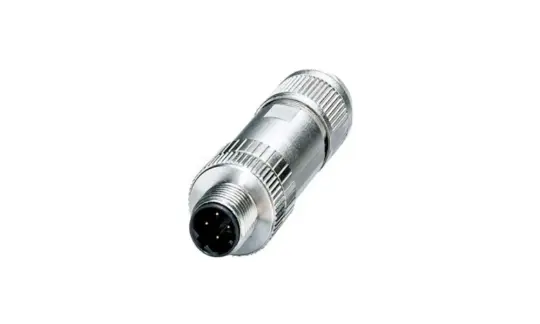
9.2 M12 Ethernet (D-coded / X-coded) connectors
| Series | Pin/ Cat. | Type | Cable diameter | AWG |
| D-coded | 4-pin, Cat.5 | Straight or 90°, metal housing | 4.0–8.0 mm 5.0–9.7 mm (806205) | 20–26 |
| X-coded | 8-pin, Cat.6A | 4.0–8.0 mm 5.0–9.7 mm (806206) | 22–26 |
All versions are rated IP67 and UL-approved. The D-coded versions comply with PROFINET requirements.
9.3 M12 cable assemblies
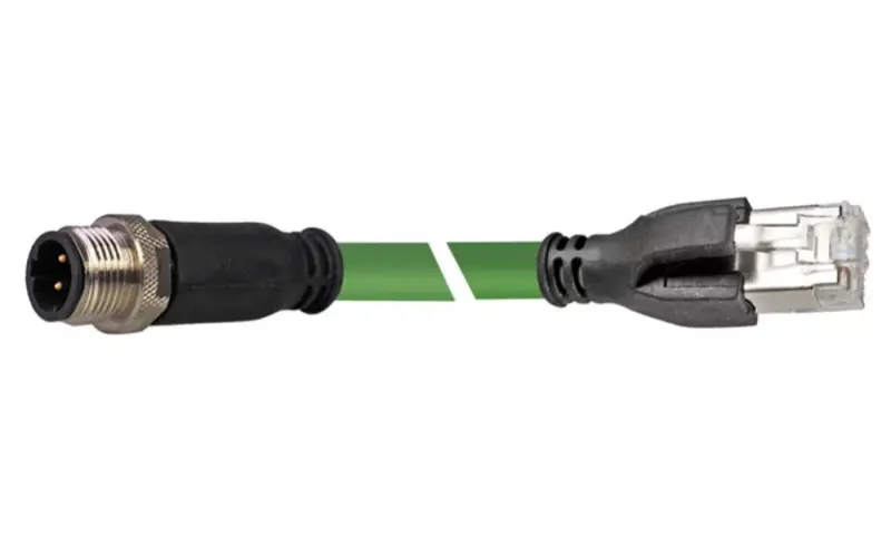
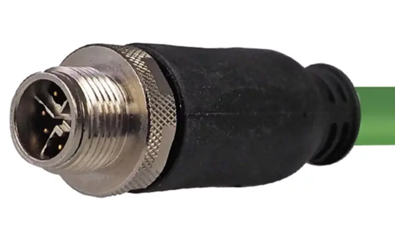
HELU pre-assembled M12 cables are defined by two factors: the connector at each end and the cable in between. Choose the connectors based on the devices you need to connect, and choose the cable based on the installation type.
Four connector combinations are available:
| Type | End A | Head B |
| D-coded M12 on both ends | M12 D, straight or right-angle, IP67 | M12 D, straight or right-angle, IP67 |
| RJ45 to D-coded M12 | RJ45, 4-pin, IP20 | M12 D, straight, IP67 |
| X-coded M12 on both ends | M12 X, straight or right-angle, IP67 | M12 X, straight or right-angle, IP67 |
| RJ45 on both ends | RJ45, IP20 | RJ45, IP20 |
Cables and lengths are available for each connector type
| Cable (code) | Installation Instructions | Cat. | M12 D-coded, double-ended | RJ45 → M12 D | M12 X-coded, double-ended |
| PROFInet A, PVC (800653) | Fixed | 5 | Straight, 90°: 0.5–25 m | 0.5–100 m | |
| PROFInet B, PVC (800654) | Flexible | 5 | Straight, 90°: 0.5–25 m | 0.5–100 m | |
| PROFInet B, Green PVC (804283) | Flexible | 5 | Straight: 0.5–25 m | ||
| PROFInet C, PUR (800655) | Cable Chain | 5 | Straight, 90°: 0.5–25 m | 0.5–100 m | |
| PROFInet C, PVC (802914) | Cable Chain | 5 | Straight, 90°: 0.5–25 m | 0.5–100 m | |
| HELUKAT® 100 SF/UTP, PUR (82839) | Cable Chain | 5e | Straight, 90°: 0.5–25 m | 0.5–25 m | |
| HELUKAT® 100IND, PUR (805702) | Flexible | Straight: 0.5–25 m | 0.5–25 m | ||
| HELUKAT® 200IND SF/UTP, PUR (800068) | Flexible | 5e | Straight: 0.5–15 m | ||
| HELUKAT® 600IND S/FTP, PUR (802184) | Flexible | 6A | Straight, 90°: 0.5–25 m | ||
| HELUKAT® 500S SF/FTP, PUR (805548) | Cable Chain | 6A | Straight, 90°: 0.5–25 m |
All M12 connectors meet the IP67 rating, while the RJ45 connectors are 4-pin IP20 types. For 8-core cables, the M12 D-coded connectors are wired to only 4 pins. The products are UL/CSA certified.
Explore our full range of assembly solutions
RJ45 connectors, IP2 - RJ45 connectors, ScrewVision - ix Industrial connectors (A-coded, C-coded) - M12 connectors (M12D 180°, M12X 180°, M12D 90°, M12X 90°)
10. FAQs
Yes. Most M12 connectors are rated IP67 , and some versions reach IP69K. Note that the IP rating usually applies only when both connectors are mated and fully tightened.
Shielded versions have a metal housing connected to the cable shield, which reduces the effect of electromagnetic interference near drives and motors. Shielding performance depends on the whole system: the cable must be shielded and the shield must be correctly terminated to the connector housing. In low-noise areas, unshielded plastic versions are sufficient and more cost-effective.
No. Each coding has a different keyway to prevent incorrect mating. To connect the two types, you need a dedicated adapter cable.
The 4-pin D-coded M12 connector is the standard choice for 100 Mbit/s PROFINET. If the device also needs DC power, an L-coded M12 connector (up to 16 A) is the usual companion.
No. Speed depends on the coding, the cable category and the device, not on the connector type. RJ45 with Cat.6A components and X-coded M12 connectors both support up to 10 Gbit/s. The advantages of M12 are durability, sealing and vibration resistance.
Yes. RJ45 to M12 cables are widely used to connect field devices to switches or PLCs in the control cabinet. Make sure the M12 coding, cable category, shielding and IP rating match the application. HELU offers RJ45 to D-coded M12 cables in lengths up to 100 m.
M8 connectors have an 8 mm thread and are more compact, typically used for small sensors with few pins. M12 connectors offer more codings, carry higher currents and are more common for Ethernet and power applications.