What is electrical wiring color code? The complete wire color code chart
What is electrical wire color coding? Decode L-N-PE, three-phase, and DC (+/-) wire colors, plus a quick-reference color code chart — a guide from HELU Vietnam.
Article content:
If you've ever stood in front of a control panel in a factory, or checked the wiring connections on a production line, you've probably noticed that wires and cables differ not just in color, but sometimes also carry printed letters and numbers. In practice, wire markings fall into two completely different categories.
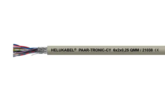
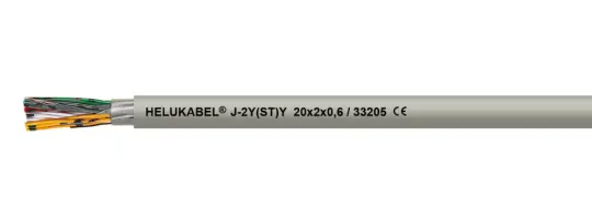
The first group consists of markings/codes printed on the cable jacket (product name, applicable standards, cross-sectional area, voltage rating, etc.) that help you identify the correct cable type and read the datasheet . If this is what you need, HELU Vietnam has a very detailed guide on this topic—check it out here.
The second group (which is also the main focus of this article), consists of the color and letter designations used in electrical systems (L, N, PE, L1, L2, L3, +/-...), which help you identify which wires are phase wires, neutral wires, or ground wires so you can make correct and safe connections in industrial electrical systems, control panels, or production lines. This is foundational knowledge that anyone working with electricity (from electrical engineers and industrial electricians to maintenance technicians and engineering students) should thoroughly understand.
1. What is electrical wire color coding, and why does it matter?
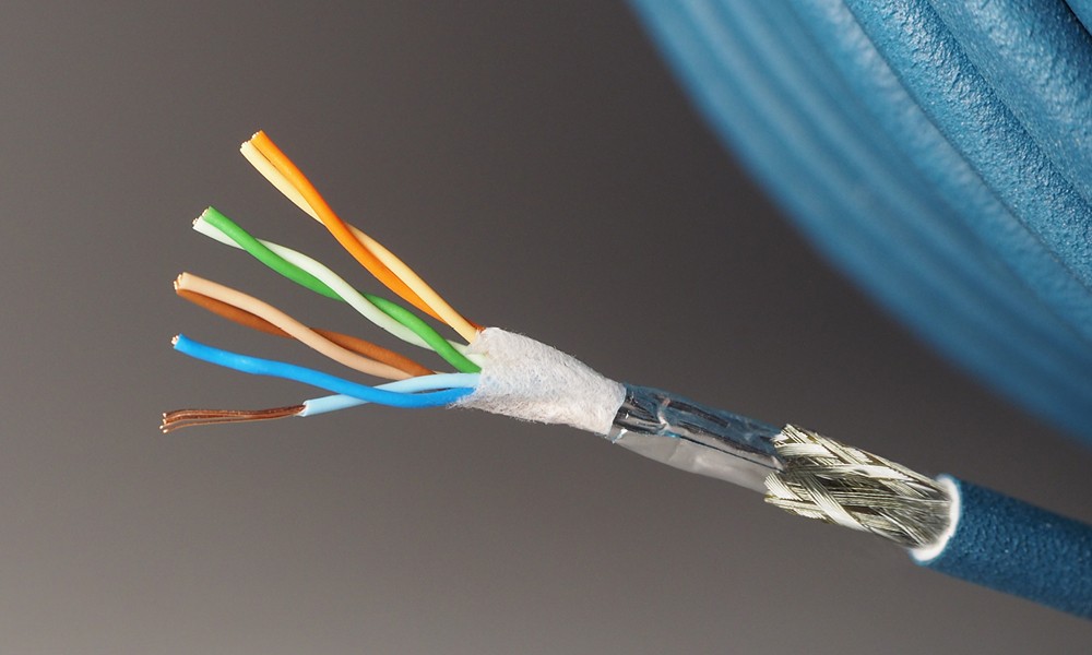
Color coding allows for quick identification of each individual strand within an electrical cable consisting of many different small strands.
1.1 What is electrical wire color coding?
Electrical wire color coding is a standardized system of colors (sometimes combined with letters) used to indicate the role of each wire in an electrical, data, or control system — which wire carries voltage, which is grounded, and which carries a signal. At first glance, it's just the color of the insulation, but it's really a shared “visual language” across the electrical industry: whether it's a simple 3-wire circuit or a factory system with thousands of connection points, standardized wire colors help prevent mistakes, speed up maintenance, and ensure compliance with safety regulations.
1.2 Why do we need wire color coding?
Wire color coding serves five main purposes:
- Safety and risk reduction: the phase wire (which carries dangerous voltage) is assigned its own color to help avoid accidental contact during installation or repair; the ground wire — which safely carries fault current to earth — is also clearly marked so it isn't confused with the phase or neutral wire.
- Fast circuit identification: in complex systems, engineers and technicians need to quickly distinguish power circuits, control circuits, and signal circuits; wire color lets them trace a system visually instead of relying only on labels or diagrams.
- Standardization for regulatory compliance: standards such as NEC, IEC, and ANSI/TIA require or recommend specific wire colors to ensure compatibility and safety across systems; regulatory or insurance inspections also often check compliance with these color codes.
- Faster installation and maintenance: predefined wire colors reduce human error and let even less experienced technicians install wiring correctly with minimal training.
- Distinguishing voltage levels within the same facility: many factories run multiple voltage levels in parallel; wire/cable color helps technicians immediately recognize which circuit belongs to which voltage level, reducing the risk of miswiring during expansion or maintenance.
2. AC and DC wire color conventions
2.1 L, N, PE — Phase, neutral, and ground wires (single-phase)
The three markings you'll encounter most often when working with single-phase electrical systems are:
- L (Line/Live): the phase wire, also called the hot wire, carrying voltage from the source to the load.
- N (Neutral): the neutral wire, carrying current back to the source to complete the circuit.
- PE (Protective Earth): the protective ground wire, which only carries current to earth in the event of a fault, protecting both people and equipment.
According to the international standard IEC 60446 (2007 edition) — now merged into IEC 60445 (2010 edition) — wire colors are specified as follows:
- A single phase wire uses brown; if there are multiple phase wires, the additional ones use black and grey.
- The neutral wire (N) uses light blue.
- The protective ground wire (PE) uses green-yellow (a two-color stripe combination).
- For a PEN wire (combined neutral and protective conductor in a TN-C system), the standard specifies green-yellow or light blue, with cross-reference marking at both ends.
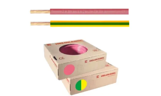
| Marking | Meaning | Colors according to IEC 60445/60446 |
| L (L1) | Phase / live wire | Brown (single phase); Black, Grey (multiple phases) |
| N | Neutral wire | Light blue |
| PE | Protective / ground wire | Green–Yellow (2-color stripe) |
| PEN | Combined neutral/protective (TN-C) | Green-Yellow or Light blue, marked at both ends |
2.2 Wire color coding for three-phase systems — L1, L2, L3
In three-phase electrical systems, each phase wire is marked individually as L1, L2, L3 (some older European documents use R, S, T), along with the neutral wire N and ground wire PE as described above.
Common wire colors for three-phase systems are as follows:
- Phase wire L1 is brown
- Phase wire L2 is black
- Phase wire L3 is grey
- Neutral wire (N) is light blue
- Ground wire (PE) is green-yellow striped
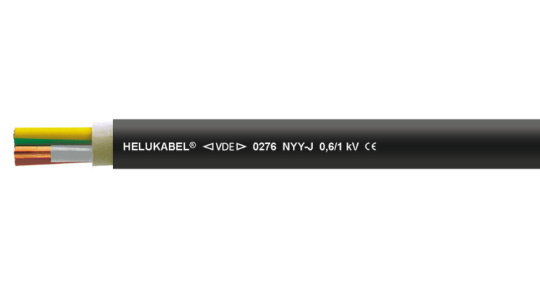
For three-phase systems, there's an important point to note: three-phase wire colors are not completely standardized worldwide, even within regions that follow IEC. Here are some examples of color schemes (phase/neutral & ground) recorded in different countries:
| IEC and UK (New Color Codes) | Old UK Color Code | North America (NEC and CEC) | |
| Phase wire L1 | Brown | Red | Black |
| Phase wire L2 | Black | Yellow | Red |
| Phase wire L3 | Grey | Blue | Blue |
| Neutral wire N | Light blue | Black | White |
| Ground wire PE | Green-yellow | Green-yellow | Green, green-yellow, or bare copper |
2.3 Positive/negative wire coding (DC)
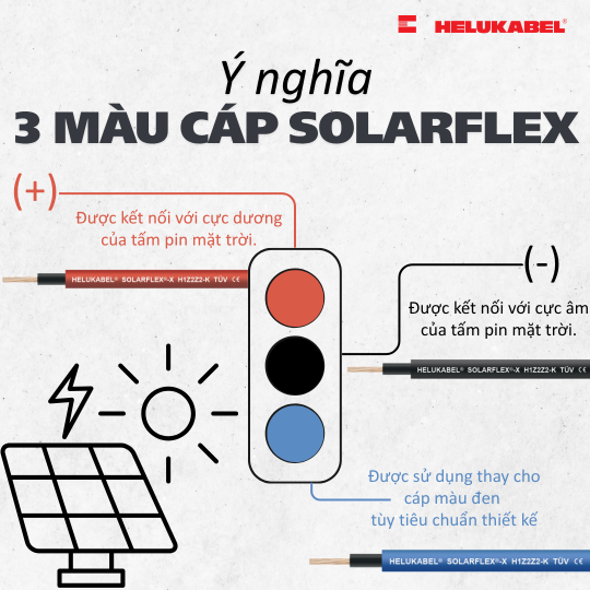
For DC (direct current) circuits — such as batteries and solar power systems — the common convention in practice is to use red for the positive terminal (+) and black for the negative terminal (–). This convention is widely used in electronic devices and battery systems in general, and differs from the L-N-PE system used specifically for AC (alternating current) systems described above.
If a DC circuit has a separate ground wire (in addition to the two +/- wires), it's usually white or grey.
Keep in mind this is a common industry convention, not a single universally mandatory color standard for every DC system worldwide — so for high-power systems like solar power, always check the +/- markings printed directly on the terminals or cable jacket rather than relying on color alone. Dedicated DC cables, such as HELU's SOLARFLEX solar cable, typically have polarity markings printed clearly on the jacket to minimize the risk of reverse-polarity connections during installation.
💡Understanding the meanings of the three DC cable colors in SOLARFLEX photovoltaic systems
3. Wire color coding for multi-core cables
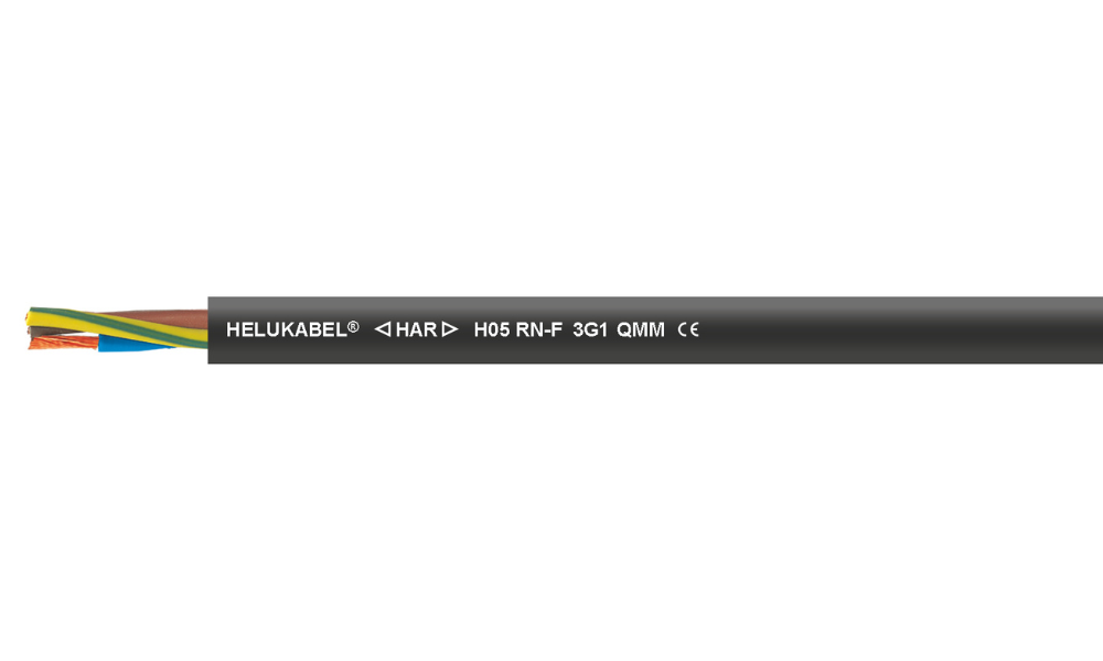
H05RN-F / 05RN-F rubber cables are color-coded in accordance with the DIN VDE 0293-308 standard
3.1 Wire color coding per the DIN VDE 0293-308 standard
The three sections above covered the role of each wire (phase, neutral, ground, or +/-). This section addresses a different question: when several such wires are bundled together in a single multi-core cable, how is each core marked?
For cables with just a few cores (2-5 cores), each core can still be distinguished by its own color following the L-N-PE or three-phase convention described above. For example, with 3-core cable — the most common type in this group — 3-core wire color rules aren't a separate color chart at all; they still follow the same L-N-PE (or L1-L2-L3) convention from sections 1-2. But as the number of cores increases — common in control cables and multi-core signal cables used in industry — assigning each core its own distinct color becomes impractical, since more colors mean a higher risk of confusion during wiring.
According to the DIN VDE 0293-308 standard for cable core identification, the conversion rule is as follows:
- The protective ground wire (if present) keeps its usual green-yellow color.
- From 6 cores upward, all remaining cores switch to the same black color and are printed with sequential numbers (1, 2, 3...) along the core to distinguish them, instead of using multiple colors.
This is why, when you cut open a multi-core control cable, you typically see black cores with small printed numbers along their length instead of the multiple colors seen in single wires or 2-5 core cables.
Note: The rule above commonly applies to control cables manufactured to European standards (DIN VDE). The exact core-count threshold and numbering method may vary by product line/manufacturer — always check the datasheet for the specific cable in question.
3.2 Other specialized wire/cable color coding systems
Beyond the general rule above, the cable industry has many more specialized color/numbering systems, typically used internally in manufacturing and on individual product datasheets, for example:
- DIN 47100: a core color code for electronic control and computer cables, combining base color and ring color to number more than 60 cores.
- Manufacturer-specific color-coding systems: For example, HELU’s TRAYCONTROL 300 / TRAYCONTROL 300-C control cable series uses a proprietary color-coding scheme for up to 50 conductors: The first 10 conductors use solid colors in the following order: black – brown – red – orange – yellow – green – blue – purple – gray – white. After that, the system switches to a “white + another color” combination (white/black, white/brown, etc.) to accommodate a greater number of conductors while still allowing for easy visual identification.
- Color codes for switchboard cable, bundled/quad installation cable, and outdoor telecom cable: each with its own color grouping/numbering rules.
- Core color codes for automotive (single-core automotive) cable: using combinations of base color, longitudinal stripe, and marking rings to distinguish hundreds of wire types inside a vehicle.
These are all fairly specialized systems, typically only needed when working directly with the datasheet of a specific cable line. If you're selecting or wiring a specialty multi-core cable, HELU's technical team is always ready to advise and provide the correct color chart for the product you're using.
4. Wire symbols on electrical drawings and diagrams
Different from the physical wire colors discussed above, when reading a CAD drawing or an electrical schematic, you'll encounter an entirely different set of symbols — conventional graphic symbols for wires, connection points, switching devices, outlets, grounding, and so on. The graphic symbol set used in electrical diagrams is internationally standardized under IEC 60617 – “Graphical symbols for diagrams,” which many national standards reference when building electrical engineering drawings.
Some basic symbol groups commonly found on electrical diagrams include: wire and connection-point symbols (straight lines, dots at junction/connection points), grounding symbols, circuit breaker/MCB/fuse symbols, and outlet/switch symbols.
Important reminder: symbols on a drawing are used for designing and reading an electrical system on paper or in software, and are entirely different from the physical colors and markings printed on actual wires described in the sections above.
5. Electrical wire color code chart — quick reference for AC/DC and abbreviations
5.1 Quick reference: AC and DC wire colors
| Symbol | Meaning | Colors / Common Conventions |
| L / L1 | Phase wire (single-phase) / Phase 1 (three-phase) | Brown (IEC); US practice: black (120/208V) |
| L2 | Phase 2 (three-phase) | Black (IEC); US practice: red |
| L3 | Phase 3 (three-phase) | Grey (IEC); US practice: blue |
| N | Neutral wire | Light blue (IEC) |
| PE | Protective / ground wire | Green–Yellow (IEC) |
| PEN | Combined neutral/protective | Green-Yellow or light blue, marked at both ends |
| + / – | Positive/negative terminal (DC) | Red (+) / Black (–) — common convention; check equipment markings |
5.2 Quick reference: Wire color abbreviations per IEC 60757
On cable datasheets or catalogs, wire colors are often abbreviated with two letters rather than spelled out in full. The most common abbreviation set, per IEC 60757, is as follows:
| Color | IEC 60757 code | Symbols according to the German standard (new) | Symbols according to the (old) German standard |
| Black | BK | SW | bw |
| Brown | BN | BR | br |
| Red | RD | RT | rt |
| Orange | OG | OR | or |
| Gold | YE | GE | ge |
| Green | GN | GN | gn |
| Blue | BU | BL | bl |
| Purple | VT | VL | vi |
| Gray | GY | GR | gr |
| White | WH | WS | ws |
| Hong | PK | RS | rs |
| Blue | China | TK | tk |
When combined, the ground wire code (green-yellow) is typically abbreviated as GNYE (joining GN and YE). Knowing this abbreviation set helps you read multi-core cable datasheets quickly without having to look up the full color name every time.
6. Wire color coding for other specialized applications
6.1 Wire color coding for networking and data systems (data, ethernet)
For network and data cables (Ethernet, fiber optic, PoE), color coding is no longer based on electrical role (phase/neutral/ground), but on the function of the connection within the network system.
Structured cabling standards such as ANSI/TIA-606-B (US) and ISO/IEC 11801 (international) mainly govern labeling and system documentation; while cable performance/connector standards like TIA/EIA-568 (Cat5e, Cat6, Cat6A, etc.) also don't mandate a specific cable jacket color. In other words, unlike the L-N-PE/three-phase/DC coding covered in earlier sections, network cable color is mainly an internal convention set by each organization/IT team, not a legal requirement.
💡Learn the color sequence of LAN cables according to the T568A and T568B standards
That said, there is a fairly common color convention adopted by many technical teams/data centers for easier management and quick reference:

| Color | Common functions |
| Blue | Standard LAN/data connection |
| Yellow | PoE (Power over Ethernet) — IP cameras, access points |
| Red | VoIP, critical/emergency systems |
| Green | Crossover / test connections |
| Orange | Demarcation point / handoff with the carrier |
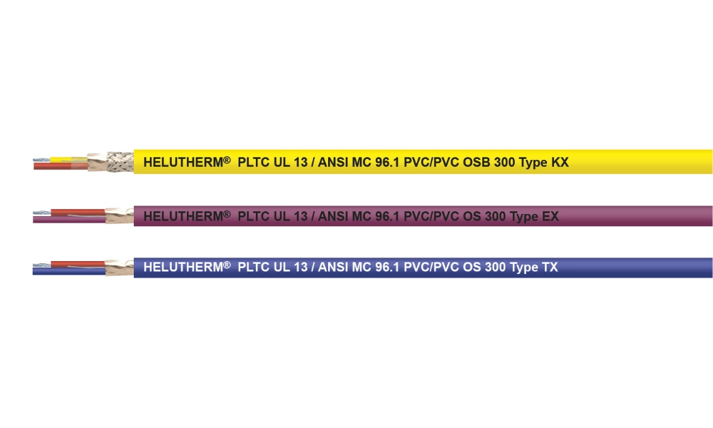
HELUTHERM® PLTC UL 13 / ANSI MC 96.1 PVC/PVC thermocouple extension cable
6.2 Wire color coding for thermocouple and compensating cables
This is a fairly specialized color-coding system used in industrial temperature measurement with thermocouples — completely different from the power/network coding systems described in the previous sections. Thermocouples can operate in harsh environments at temperatures exceeding 1000°C, so a compensating or thermocouple extension cable is needed to carry the signal to a receiver/reader located in a safe area.
Both types of cables consist of at least one pair of "+" and "–" wires, made from two different metals or alloys to provide the appropriate thermoelectric properties. The difference: thermocouple cables (thermoelectric, designated X) are made from the exact same materials as thermocouple probes; compensating cables (designated C), on the other hand, are made from alternative materials that offer equivalent properties at a more reasonable cost.
| Type | Materials (+ / –) | Operating temperature range (according to IEC 584-3) |
| R | PtRh13 / Pt | 0°C to 1600°C |
| S | PtRh10 / Pt | 0°C to 1600°C |
| B | PtRh30 / PtRh6 | 600°C to 1700°C |
| J | Fe / CuNi | -40°C to 750°C |
| T | Cu / CuNi | -40°C to 350°C |
| E | NiCr / CuNi | -40°C to 900°C |
| K | NiCr / NiAl | -40°C to 1200°C |
| N | NiCrSi / NiSi | -40°C to 1200°C |
Each thermocouple type above has its own jacket and core (+/–) color coding to prevent reverse-polarity connections — a serious error, since it produces an incorrect reading with no obvious warning. Under the current international standard IEC 584-3 (now IEC 60584-3), the common color convention is as follows:
| Type | Jacket color (+) | (–) color | Cable jacket temperature range |
| T | Brown | White | -25°C to +100°C |
| J | Black | White | -25°C to +200°C |
| E | Violet | White | -25°C to +200°C |
| K | Green | White | -25°C to +200°C |
| N | Pink | White | -25°C to +200°C |
| R / S | Orange | White | 0°C to +200°C |
| B | Grey | White | 0°C to +100°C |
7. FAQs
L (Live) is the phase/hot wire, N (Neutral) is the neutral wire, and PE (Protective Earth) is the protective ground wire. Per IEC 60445/60446, the corresponding conventional colors are brown, light blue, and green-yellow.
The markings are L1, L2, L3 (or R, S, T). For reference, IEC-based coloring can be: L1 black, L2 brown, L3 grey. However, actual colors can vary between countries and systems, so always test with a meter before connecting.
It's the +/- polarity marking used for DC circuits, such as batteries and solar power systems. The common convention is red for the positive terminal and black for the negative terminal.
This is due to differing histories of electrical standard development across regions. The IEC is working to harmonize color conventions among member countries, but significant differences still remain in electrical design and installation requirements between countries.
Symbols on a drawing (per IEC 60617) are conventional graphic symbols used for designing/reading an electrical system diagram on paper or in CAD software — completely different from the color/markings printed directly on physical wires.
These are cable-type codes printed on the jacket (not connection color codes) — commonly found on residential electrical cable lines in Vietnam. See the full guide to reading product codes and datasheets in HELU's in-depth article: A complete guide to reading product codes and the datasheet .
Standards such as ANSI/TIA-606-B, ISO/IEC 11801, and TIA/EIA-568 mainly govern labeling, categories, and pinouts — they don't mandate a specific cable jacket color. Function-based patch cord/cable colors (LAN, PoE, VoIP, etc.) are typically an internal convention set by each organization/systems integrator rather than a hard standard requirement.
Yes. Many industries apply their own specialized standards, for example ISO 6722 for automotive/EV wiring, NFPA 72 for fire alarm systems, NEC Article 690 for solar power systems, and NFPA 79/EN 60204-1 for industrial machinery. That means a wire/cable color suitable for a residential application may not meet the correct standard when used in a different specialized application.
No. This is an entirely separate system, used for industrial temperature measurement (not power distribution), with color codes based on thermocouple type (T, J, K, E, N, R, S, B) that also vary by national standard (IEC 584-3, ANSI MC96.1, BS 4937, NF C 42-324, DIN 43710).