24kV/35kV medium voltage underground cables: Construction, classification, and installation guide
Two medium voltage underground cables on the market may both be labeled “24kV”, yet carry different Uo/U(Um) ratings on their datasheets — and aren't always interchangeable. Because these cables are buried underground, any mistake in construction, voltage rating, or installation is far harder and more costly to fix than with overhead cables. This article covers cable construction, how to correctly read Uo/U(Um) voltage ratings, installation standards, and HELU's range of medium voltage cables and accessories.
-
1Underground medium-voltage cables and their advantages
-
2Applications of underground medium voltage cables
-
3Cable construction #1: Conductor
-
4Cable construction #2: Conductor shield
-
5Cable construction #3: Insulation
-
6Cable construction #4: Insulation shield
-
7Cable construction #5: Metallic shield
-
8Cable construction #6: Outer sheath
-
9Uo/U(Um) designation and 24/35kV cable naming conventions
-
10Water treeing & electrical treeing in underground MV cables
-
11Installation guide for medium voltage underground cables
-
12HELU MV cables: XLPE insulation, PE sheath
-
13HELU MV cables: XLPE insulation, PVC sheath
-
14HELU MV cables with water-blocking properties
-
15HELU MV cables: TR-XLPE insulation, LLDPE jacket
-
16HELU MV cables: TR-XLPE insulation, PVC sheath
-
17HELU MV cable terminations and joints
1. Understanding medium voltage underground cables
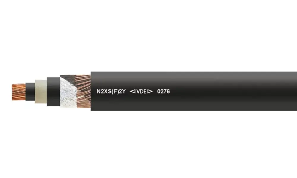
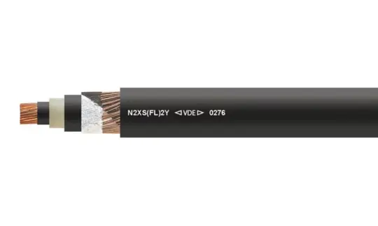
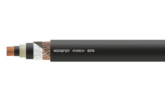
N2XS(F)2Y underground power cable, rated at 6/10 kV, 12/20 kV, and 18/30 kV, with XLPE insulation and a PE jacket
1.1 What are medium voltage underground cables?
Medium voltage underground cable is a power cable buried directly in the ground and used to transmit electricity at medium voltage levels — by common industry classification, medium voltage cable spans roughly 1kV to 35kV, with 22–24kV and 35kV being the two most widely used classes in Vietnam. It forms a critical link in the distribution network, connecting intermediate substations to load substations (factories, industrial parks, buildings, and residential areas).
Compared with low voltage underground cable (which feeds loads directly), medium voltage cable has thicker insulation and additional semi-conductive layers and a metallic shield to withstand a higher electric field. On routes running through densely built areas, under vehicle traffic, or exposed to mechanical stress, the cable may also include an armor layer to withstand impact, soil pressure, and friction during installation.
Key advantages include:
- Space savings and improved urban aesthetics: no need for the wide right-of-way required by overhead lines, making it well suited to densely populated areas.
- Greater reliability against weather: less affected by lightning, storms, or ice compared with overhead cable, and no risk of impact from vehicles or falling objects.
- Operational safety: lower risk of electric shock or fire from broken conductors or falling poles, as can happen with overhead lines.
- For armored cable variants, better resistance to mechanical stress and corrosion, making them suitable for routes with vehicle traffic, construction activity, or damp/corrosive environments.
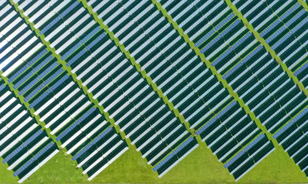
Medium-voltage cables are a critical component of renewable energy projects (solar power, wind power)
1.2 Applications of medium voltage underground cables
- Urban distribution networks: connecting intermediate substations to load substations in densely populated areas.
- Industrial parks and export processing zones: supplying factories and production lines that require large, stable power capacity.
- Commercial and critical infrastructure requiring high reliability: office buildings, data centers, hospitals — where power outages cause significant losses.
- Areas with high building density or heavy traffic: utility tunnels, roads carrying heavy vehicles — typically using armored cable to withstand mechanical stress.
- Connecting renewable energy projects (solar, wind) to the medium voltage distribution grid.
2. Construction of medium voltage underground cables
A medium voltage underground cable is built, from the inside out, of six main layers:
| Layer | Typical material | Function |
| 1. Conductor | Copper or aluminum | Carries the required load current |
| 2. Conductor shield | Extruded semi-conductive compound | Smooths out the electric field around the conductor surface, which is never perfectly smooth, ensuring intimate contact with the insulation |
| 3. Insulation | Cross-linked polyethylene | Withstands operating voltage as well as voltage surges from lightning strikes |
| 4. Insulation shield | Extruded semi-conductive compound | Smooths out the electric field around the insulation, ensuring intimate contact and preventing ionization in any air gaps between the insulation and the metallic shield |
| 5. Metallic shield | Copper wires, copper tape, or lead sheath | Establishes a ground potential and a path for the insulation's capacitive current; carries single-phase-to-ground fault current |
| 6. Outer sheath | PE or PVC (or LSZH where low-smoke, halogen-free properties are required) | Protects all inner layers from mechanical impact, chemicals, heat, and moisture in the buried environment |
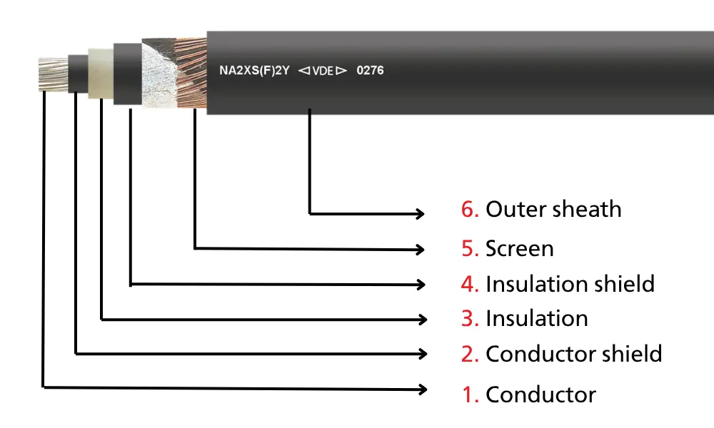
Construction of underground medium voltage cables
2.1 Conductor
Most medium voltage underground cables use stranded copper or aluminum conductors. The cross-section, diameter, and number of strands are standardized (per AWG/MCM under North American standards, or mm² in Vietnam) independent of whether copper or aluminum is chosen.
The outer surface of the conductor is usually compact-round compressed to be nearly perfectly smooth. This reduces cable flexibility somewhat, but in exchange prevents air voids that could ionize and cause partial discharge right at the inner surface of the insulation — the point of highest voltage gradient.
Conductor choice also differs between distribution cable and cable used in industrial plants:
- Distribution cable typically uses aluminum, and at smaller cross-sections (up to about 2/0 AWG for aluminum, 6 AWG for copper) commonly uses solid rather than stranded conductors. A solid conductor is stiffer but has the natural advantage of blocking water migration along the cable core. For stranded conductors at larger cross-sections, manufacturers achieve the same water-blocking effect by adding water-swellable powder or filling compound between the strands.
- By contrast, in applications demanding maximum reliability, such as power plants, stranded copper conductors remain the standard choice despite their higher cost compared with aluminum.
2.2 Conductor shield
The conductor shield is a thin extruded semi-conductive layer (about 0.25–0.5mm) compatible with the primary insulation material, applied directly over the conductor. Its role is to eliminate the air gap between the conductor and the insulation — the location most prone to ionization. Together with the insulation shield on the outside, these two layers act like the plates of a capacitor, helping the electric field distribute evenly and symmetrically around the insulation rather than concentrating locally.
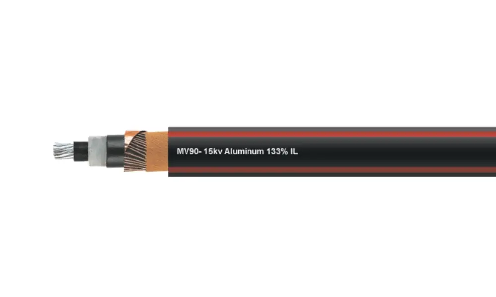
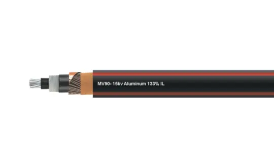
MV90 Medium-Voltage Cable – 15 kV Aluminum 133% IL, aluminum conductor, TR-XLPE insulation
2.3 Insulation
The main insulation layer must have sufficient dielectric strength to withstand both normal operating voltage and abnormal voltage surges such as lightning strikes or switching transients. For medium voltage underground cable, XLPE remains the most common material.
A notable improvement is TR-XLPE (tree-retardant XLPE) — an additive to the base XLPE formulation that significantly slows the formation and growth of water treeing, although it does not eliminate the phenomenon entirely.
In certain specialized applications (short cable runs, extremely high reliability requirements), EPR rubber is also used in place of XLPE because it withstands electrical stress and partial discharge better — at the cost of higher dielectric loss (a dielectric constant of about 3.2 versus about 2.3 for XLPE), making it less suitable for the long distribution runs typical of standard medium voltage grids.
💡Learn about the properties of XLPE material - HELU's XLPE cable lines
2.4 Insulation shield
Beyond creating a grounded surface around the insulation to distribute the electric field symmetrically, this shield layer serves three lesser-known roles: reducing radio-frequency interference generated by the cable, enabling insulation testing of individual conductors, and, when properly grounded, reducing the risk of electric shock to personnel working near the cable.
Structurally, the shield consists of two parts: the extruded semi-conductive insulation shield (common in modern cables) and the overlying metallic shield. The metallic shield is typically helically applied overlapping copper/brass tape, or concentric copper wires around the insulation; another variant ("Unishield") embeds flat or corrugated wires directly in the extruded semi-conductive jacket instead of using a separate tape wrap.
2.5 Metallic shield
For the metallic shield, the distribution industry has long favored wire-type designs — flat strap and round wire — with various neutral conductor cross-sections (sized as a ratio to the phase conductor) to balance neutral/fault current carrying capacity against the desire to reduce cost and cable weight.
A helically applied copper tape design, with a nominal thickness of about 0.125mm, is also still used. Under normal operating conditions, both wire and tape designs perform the two core functions — discharging accumulated charge from the semi-conductive layer and carrying sufficient fault current. The difference between the two lies mainly in cost, weight, and whether an outer sheath is still needed, not in operational safety.
2.6 Outer sheath
The outer sheath protects the insulation and inner shield layers from mechanical damage and, to some extent, environmental exposure. It's worth noting, however, that the jacket only slows — rather than fully prevents — moisture ingress into the cable core if the cable remains submerged continuously for an extended period (years). This is why, even with a good jacket, the quality of watertight terminations and joints — not the jacket alone — is what ultimately determines the real-world service life of a cable route.
Common jacket materials include PVC, and for higher moisture resistance, linear low-density polyethylene (LLDPE) — preferred in the distribution industry for its superior resistance to moisture diffusion compared with PVC. In applications with strict flame-spread requirements (power plants, buildings, utility tunnels), the jacket is typically neoprene or CSPE (chlorosulfonated polyethylene) instead of standard PE.
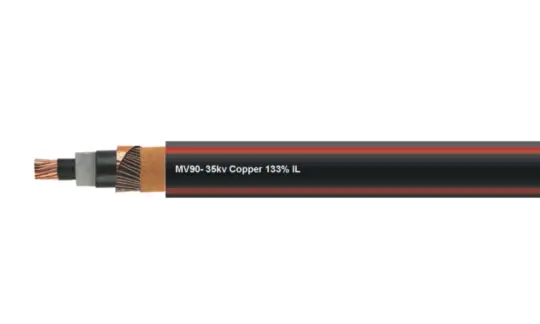
3. The Uo/U(Um) rating and how 24kV / 35kV medium voltage underground cable is named in the market
Reading a medium voltage cable catalog, you'll see a rating written as Uo/U(Um) rather than a single voltage figure. These values mean:
- Uo: the rated voltage between phase conductor and ground/metallic shield.
- U: the rated voltage between phase conductors (the rated voltage of the grid).
- Um: the maximum system voltage the cable can withstand.
The "24kV" or "35kV" commonly used in the market is actually shorthand based on U or on the grid voltage class, not the full Uo/U(Um) designation. Conversion table:
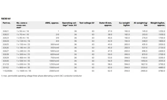
| Uo/U | Corresponding um | Commonly referred to in the market as |
| 6/10 kV | 12 kV | 10kV/12kV class |
| 12/20 kV | 24 kV | 22kV/24kV class |
| 18/30 kV | 36 kV | 35kV/36kV class |
One additional point: two cables with different Uo/U ratings can still be used interchangeably if they share the same Um value — because Um is the parameter that determines whether a cable is suitable for a given grid, while Uo/U simply reflects the specific connection configuration. For example, both 12/20(24)kV cable and 12.7/22(24)kV cable can be used on a system not exceeding 24kV, since both share Um = 24kV — which is also why some catalogs list both ratings side by side for the same grid voltage class.
For example, HELU’s medium-voltage cable catalog currently uses this standard notation: 6/10 kV, 12/20 kV, 18/30 kV—where 12/20 kV corresponds to “24 kV” and 18/30 kV corresponds to “35 kV” in common usage.
4. Common causes of medium voltage underground cable failure
Despite having multiple protective layers — especially the durable XLPE insulation — this insulation can still degrade through two common mechanisms seen in underground cables:
- Water treeing: forms when moisture penetrates the insulation through microscopic defects, creating a branching, tree-like network of water-filled channels (each droplet only about 0.1–1 micrometer) under the effect of a sustained electric field. Cables rated 6kV and above are considered especially susceptible to this phenomenon. This is why the outer jacket — and especially cable joints and terminations — must be completely watertight, since most underground cable failures originate at connection points rather than in the cable body itself.
- Electrical treeing: develops from partial discharge at defect sites or impurities within the insulation, gradually forming branching conductive channels that can lead to complete breakdown if not detected early.
These degradation mechanisms are not solely the result of natural aging of the insulation material — in large part, they originate from the installation process itself.
5. Installation guide for medium voltage underground cables
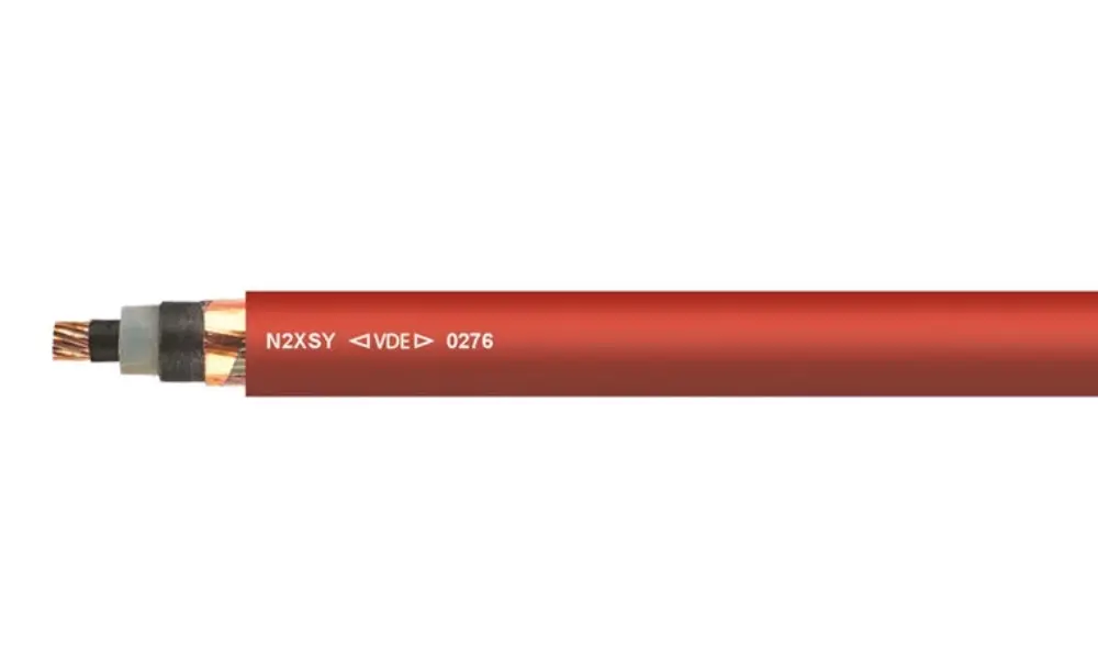
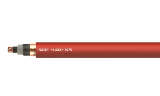
N2XSY medium-voltage cable, red PVC jacket
Medium voltage underground cable requires an installation procedure that differs substantially from low voltage or general household electrical cable. The guidance below summarizes the installation instructions for HELU's medium voltage cable range, compiled according to DIN VDE 0276-620:2018-04/HD 620 S2:2010 and IEC 60502-2.
5.1 Application range and installation temperature
Medium voltage cables rated 6/10kV, 12/20kV, and 18/30kV can be installed indoors, in cable ducts, outdoors, buried directly in the ground, or underwater. Red PVC-jacketed cable requires additional protective measures when installed outdoors.
The minimum allowable cable temperature during installation is -5°C for PVC jacket and -20°C for PE jacket. If the cable temperature is below this threshold, it must be warmed to at least the minimum allowable temperature before installation — a process that can take up to two days and must be factored into planning before pulling cable in cold weather.
5.2 Bending radius
For XLPE-insulated cable, the bending radius must not be smaller than 15 times the cable's outer diameter. This can be reduced to half that value (7.5 times the diameter) only when all three of the following conditions are met simultaneously:
- The bend is made only once, at a single location (for example, at a cable termination)
- The cable temperature is no lower than 30°C
- The bend is formed using a preset mold or forming roller rather than free bending
Bending beyond this limit can cause the conductor shield and insulation shield to separate from the insulation surface, inadvertently recreating the same ionized air gap that these two shield layers were designed to eliminate in the first place — an ideal starting point for electrical treeing.
Learn about the significance of the bending radius for electrical cables
5.3 Burial depth and installation methods
Direct burial cable is considered to have adequate mechanical protection without any additional protective layer, at a minimum depth of 0.6m in ordinary ground and 0.8m under roadways, per manufacturer recommendation. If the actual depth is shallower than this, corresponding additional protection must be added.
Besides direct burial, cable can also be installed by cable ploughing or pulled through a pre-formed duct created by horizontal directional drilling (HDD). When installed in a duct or formed conduit, the duct's internal diameter must be at least 1.5 times the cable's outer diameter, and measures should be taken to prevent silt buildup inside the duct.
5.4 Fixation of the cable
The maximum horizontal spacing between fixing clamps is 20 times the cable diameter (up to 80cm maximum); the maximum vertical spacing is 150cm. Single-core cables can be installed individually or bundled together — if bundled, they must be treated as multi-core cable for fixing purposes.
When installing single-core cable, plastic clamps or non-magnetic metal clamps should be used. Steel clamps are only permitted if the magnetic loop formed by the clamp does not enclose each individual cable core separately, to avoid localized heating from induction effects. Clamps must be tightened securely while still allowing for thermal expansion of the cable without causing damage.
5.5 Tensile force
The maximum tensile force
is determined based on three cases:
- Conductor with pulling eye: maximum tension = total conductor cross-section × allowable tension per unit cross-section (copper: 50 N/mm², aluminum: 30 N/mm²). Note that only the conductor cross-section is counted — not the cross-section of the metallic shield, concentric neutral wires, or armor layer.
- Cable Grip with effect on the conductor: applies when pulling cable with thermoplastic insulation/jacket and no outer metallic covering, using the same formula and values as above.
- Cable Grip with effect on the sheath: maximum tension P = 3D² (N), where D is the cable's outer diameter in millimeters.
6. HELU medium voltage underground cable and accessories range
6.1 Medium voltage underground cable, XLPE insulation, PE jacket
HELU offers a range of underground medium-voltage cables with aluminum and copper conductors, including:
| Products | Cross-section | Part No. |
| NA2XS(F)2Y | 35–1,000 rm | 32600 |
| N2XS(F)2Y | 35–630 rm | 32560 |
| N2XS2Y | 35–800 rm | 32480 |
| NA2XS2Y | 50–630 rm | 32520 |
| N2XS(FL)2Y | 35–630 rm | 33054 |
| NA2XS(FL)2Y | 50–630 rm | 38062 |
6.3 Medium voltage cable with water-blocking properties
Water blocking at the conductor and/or metallic shield limits how far water can travel along the cable if the jacket is damaged, significantly reducing the length of cable that needs to be replaced or repaired. This property is achieved by adding water-swellable material inside the conductor and above/below the metallic shield.
In HELU's medium voltage underground cable range, depending on the product line and shield construction, customers can choose cable with lateral water blocking only, longitudinal water blocking only, or both layers of protection — depending on the requirements of the installation environment.
| Products | Part No. | |
| NA2XS(F)2Y | longitudinally waterproof | 32600 |
| N2XS(F)2Y | longitudinally waterproof | 32560 |
| N2XS(FL)2Y | longitudinally and laterally waterproof | 33054 |
| NA2XS(FL)2Y | longitudinally and laterally waterproof | 38062 |
6.4 TR-XLPE insulated medium-voltage cable with LLDPE jacket
| Products | Part No. |
| MV90 - 15 kV Aluminum 100% IL | 18089506 |
| MV90 - 15 kV Aluminum - 100% IL - Copper Tape Shield | 18089470 |
| MV90 - 15 kV Copper (100% IL) - Copper Tape Shield | 18089467 |
| MV90 - 15 kV Copper - 133% IL - Copper Tape Shield | 18089469 |
| MV90 - 25 kV Aluminum 100% IL | 18089498 |
| MV90 - 25 kV Aluminum - 133% IL - Copper Tape Shield | 18089472 |
| MV90 - 25 kV, 100% Copper, IL | 18089502 |
| MV90 - 35 kV Copper - 133% IL - Copper Tape Shield | 18089473 |
| MV90 - 35 kV Copper 133% IL | 18089496 |
| MV90 - 35 kV Aluminum - 100% IL | 18089475 |
6.6 Medium voltage cable terminations and joints
A termination and a joint are the points connecting cable to switchgear or connecting two cable sections together — also the most sensitive points along the entire cable route.
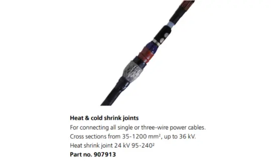
Joints are common throughout medium voltage distribution networks because, in practice, a single cable route's length usually exceeds what a standard cable drum can hold, requiring multiple cable sections to be joined to complete the route. The joint's main role is to ensure electrical and mechanical continuity at the connection point, while also controlling the electric field at the joint (stress grading) just as rigorously as at a termination. There are two types of joints for medium voltage cable: heat-shrink and cold-shrink.
HELU's medium voltage cable accessories range includes:
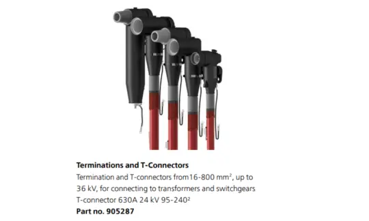
- Plug-in terminations (T-connectors): used to terminate a medium voltage cable end safely and in a controlled manner, connecting the cable to medium voltage switchgear, transformers, busbars, or outdoor connection points. See HELU's product (Part no. 905287).
- Heat-shrink joints: use heat to shrink the tubing tightly around the cable, creating a uniform, moisture-tight insulation layer and solid mechanical protection.
- Cold-shrink joints: after positioning on the cable, the installer simply removes the core support — the elastomeric material shrinks and grips the cable tightly on its own, with no heat required.